ENGINE UNIT REASSEMBLY

-
INSTALL REAR CRANKSHAFT OIL SEAL
-
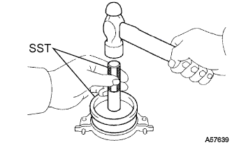
Using SST and a hammer, tap in a new oil seal until its surface is flush with the oil seal retainer edge.
- SST
- 09223-15030
- 09950-70010 ( 09951-07100 )
-
Apply MP grease to lip of the oil seal.
-
-
INSTALL REAR CRANKSHAFT OIL SEAL RETAINER
-
Install a new gasket and the retainer with the 4 bolts.
- Torque:
- 13 N*m { 133 kgf*cm, 10 ft.*lbf }
-
-
INSTALL FRONT CRANKSHAFT OIL SEAL
-
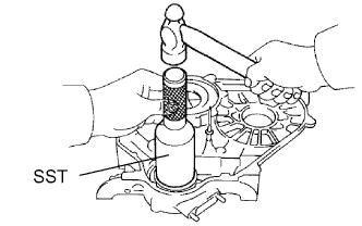
Using SST and a hammer, tap in a new oil seal until its surface is flush with the timing belt case edge.
- SST
- 09214-60010
-
Apply MP grease to the lip of the oil seal.
-
-
INSTALL TIMING BELT CASE SUB-ASSEMBLY
-
Place a new gasket on the cylinder block.
-
Install the timing belt case with the 5 bolts.
- Torque:
- 23 N*m { 230 kgf*cm, 17 ft.*lbf }
-
-
INSTALL OIL STRAINER SUB-ASSEMBLY
-
Install a new gasket and the oil strainer with the 2 bolts and 2 nuts.
- Torque:
- for nut
- 21 N*m { 210 kgf*cm, 17 ft.*lbf }
- for bolt
- 18 N*m { 184 kgf*cm, 13 ft.*lbf }
-
-
INSTALL OIL PAN SUB-ASSEMBLY
-
Remove any old packing (FIPG) material and do not drop any oil on the contact surfaces of the oil pan and cylinder block.
-
Using a gasket scraper, remove all the old packing (FIPG) material from the installation surface.
-
Thoroughly clean all components to remove all the loose material.
-
Using a non-residue solvent, clean both of the sealing surfaces.
Note
Do not use a solvent which will affect the painted surfaces.
-
-
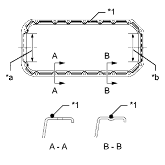
Text in Illustration *1 Seal Packing *a Timing Belt Case Contact Portion *b Rear Oil Seal Retainer Contact Portion Apply seal packing to the oil pan as shown in the illustration.
Seal packing Toyota Genuine Seal Packing Black, Three Bond 1207B or equivalent Application Specification Item Seal Packing Diameter Seal Packing Application Length Dashed line 7.0 mm (0.276 in.) 128 mm (5.04 in.) Continuous line 5.0 mm (0.197 in.) - Tech Tips
-
Do not apply an excessive amount to the surface, especially near the oil passages.
-
Parts must be assembled within 5 minutes of application. Otherwise the material must be removed and reapplied.
-
-
Install the oil pan with the 16 bolts and 2 nuts. Uniformly tighten the bolts and nuts in several steps.
- Torque:
- 18 N*m { 184 kgf*cm, 13 ft.*lbf }
-
-
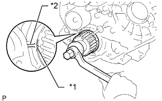
INSTALL CRANKSHAFT TIMING PULLEY
-

Text in Illustration *a Inside Align the key groove of the timing pulley with the pulley set key.
-
Using SST and a hammer, tap in the timing pulley with the flange side facing inward.
- SST
- 09223-46011
-
-
INSTALL NO. 1 TIMING BELT IDLER SUB-ASSEMBLY
-
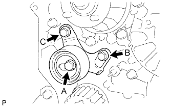
Install the No. 1 belt idler with the 3 bolts.
- Torque:
- for bolt A
- 44 N*m { 449 kgf*cm, 32 ft.*lbf }
- for bolt B, C
- 19 N*m { 195 kgf*cm, 14 ft.*lbf }
Tech Tips
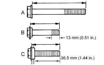
-
The bolt lengths for bolt A, B and C as follows.
-
Bolt C is combined with the No. 1 timing belt idler.
Standard Bolt Item Length A 76.5 mm (3.01 in.) B 42.9 mm (1.69 in.) C 41.3 mm (1.63 in.)
-
-
INSTALL WATER PUMP ASSEMBLY
-
Install a new gasket, the water pump and tension spring bracket with the 6 bolts.
- Torque:
- 23 N*m { 236 kgf*cm, 17 ft.*lbf }
-
-
INSTALL NO. 2 TIMING BELT IDLER SUB-ASSEMBLY
-
Install the spacer and No. 2 timing belt idler with the bolt.
- Torque:
- 33 N*m { 337 kgf*cm, 24 ft.*lbf }
-
Check that the No. 2 timing belt idler moves smoothly.
-
-
INSTALL CYLINDER HEAD GASKET
-
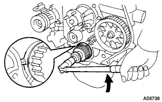
Check the piston protrusion for each cylinder.
-
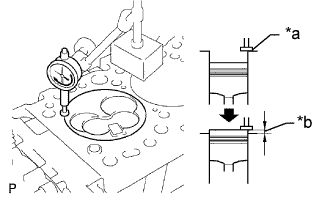
Text in Illustration *a Measuring Tip *b Protrusion Find where the piston head protrudes most by slowly turning the crankshaft clockwise and counterclockwise.
-
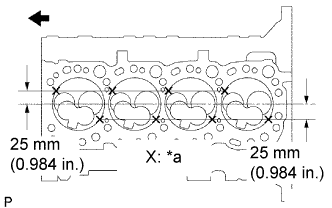
Text in Illustration *a Measuring Point 
Front Measure the protrusion of each cylinder at 2 places as shown in the illustration, making a total of 8 measurements.
-
For the piston protrusion value of each cylinder, use the average of the 2 measurements of that cylinder.
Standard protrusion 0.68 to 0.98 mm (0.0268 to 0.0386 in.) After installing the piston and connecting rod assembly, if the protrusion is not as specified, remove the piston and connecting rod assembly and reinstall them.
-
-
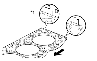
Text in Illustration *1 Cutout Mark Front Select a new cylinder head gasket.
Tech Tips
There are 3 sizes of new cylinder head gaskets, marked "B", "D" or "F" accordingly.
New Cylinder Head Gasket Thickness Item Specified Condition Mark B 1.40 to 1.50 mm (0.0551 to 0.0591 in.) Mark D 1.50 to 1.60 mm (0.0591 to 0.0630 in.) Mark F 1.60 to 1.70 mm (0.0630 to 0.0669 in.)
-
Select the largest piston protrusion value from the measurements made, then select a new appropriate gasket according to the table below.
Gasket Size Piston Protrusion Gasket Size 0.68 to 0.78 mm (0.0268 to 0.0307 in.) Use B 0.78 to 0.88 mm (0.0307 to 0.0346 in.) Use D 0.88 to 0.98 mm (0.0346 to 0.0385 in.) Use F
-
-
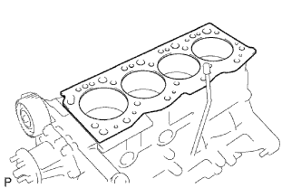
Install the selected cylinder head gasket to the cylinder block.
Note
Make sure that the gasket is installed facing the proper direction.
Be careful of the installation direction.
-
-
INSTALL CYLINDER HEAD SUB-ASSEMBLY
Tech Tips
-
The cylinder head bolts are tightened in 3 progressive steps.
-
Set the No. 1 cylinder to 90° BTDC/compression to avoid interference with the piston top and valve head.
-
If any bolt is broken or deformed, replace it.
-
Using the crankshaft pulley bolt, turn the crankshaft 90° counterclockwise, and align the timing mark of the crankshaft timing pulley with the protrusion of the timing belt case.
Text in Illustration Turn -
Place the cylinder head on the cylinder block.
Note
-
Make sure that no oil is on the mounting surface of the cylinder head.
-
Place the cylinder head on the cylinder block gently in order not to damage the gasket with the bottom part of the head.
-
-
Install the plate washers to the cylinder head bolts.
-
Apply a light coat of engine oil to the threads and under the heads of the cylinder head bolts.
-
Step 1:
-
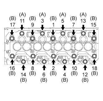
Install and uniformly tighten the 18 cylinder head bolts, in several steps, in the sequence shown in the illustrations.
- Torque:
- 78 N*m { 795 kgf*cm, 58 ft.*lbf }
Tech Tips
Each bolt length is indicated below.
Standard Bolt Item Length Bolt A 107 mm (4.21 in.) Bolt B 127 mm (5.00 in.) If any one of the cylinder head bolts does not meet the torque specification, replace the cylinder set head bolt.
-
-
Step 2:
-
Mark the front side of each cylinder head bolt head with paint.
-
Tighten the cylinder head bolts 90° in the sequence shown in step 1.
-
-
Step 3:
-
Tighten the cylinder head bolts another 90° in the sequence shown in step 1.
-
-
Check that the paint marks are now at a 180° angle to the front.
-
-
INSTALL CAMSHAFT
-
Text in Illustration *1 Timing Mark *2 Protrusion Check that the timing mark of the crankshaft timing pulley is in the position shown in the illustration.
-
Install the camshaft.
-
Place the camshaft on the cylinder head with the key groove facing upward.
-
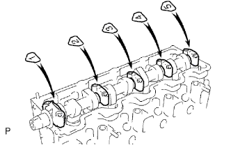
Install the 5 bearing caps in their proper locations.
-
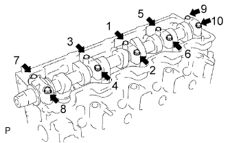
Apply a light coat of engine oil to the threads and under the heads of the bearing cap bolts.
-
Install and uniformly tighten the 10 bearing cap bolts in several steps in the sequence shown in the illustration.
- Torque:
- 25 N*m { 255 kgf*cm, 18 ft.*lbf }
-
-
-
INSTALL CAMSHAFT OIL SEAL
-
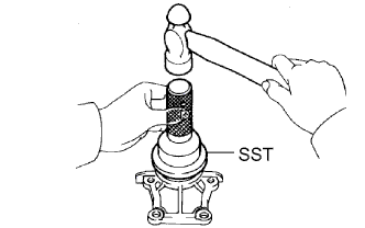
Using SST and a hammer, tap in a new oil seal until its surface is flush with the oil seal retainer edge.
- SST
- 09960-10010 ( 09962-01000, 09963-01000 )
-
Apply MP grease to the lip of the oil seal.
-
-
INSTALL CAMSHAFT OIL SEAL RETAINER
-
Install a new gasket and the retainer with the 4 bolts.
- Torque:
- 18 N*m { 184 kgf*cm, 13 ft.*lbf }
-
-
INSTALL CYLINDER HEAD COVER SUB-ASSEMBLY
-
Remove any old packing (FIPG material).
-
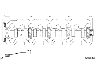
Text in Illustration *1 Seal Packing Apply seal packing to the cylinder head as shown in the illustration.
Seal packing Toyota Genuine Seal Packing Black, Three Bond 1207B or equivalent -
Install the gasket to the cylinder head cover.
-
Install the cylinder head cover with the 9 bolts and nut. Uniformly tighten the bolts and nut in several steps.
- Torque:
- 12 N*m { 122 kgf*cm, 9 ft.*lbf }
-
-
INSTALL NO. 2 TIMING BELT COVER
-
Install the timing belt cover with the 4 bolts.
- Torque:
- 18 N*m { 184 kgf*cm, 13 ft.*lbf }
-
-
INSTALL CAMSHAFT TIMING PULLEY
-
Install the woodruff key to the key groove of the camshaft.
-
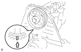
Align the timing mark on the camshaft timing pulley with the timing mark on the No. 2 timing belt cover and temporarily install the pulley with the bolt.
-
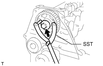
Using SST, tighten the bolt.
- SST
- 09960-10010 ( 09962-01000, 09963-01000 )
- Torque:
- 98 N*m { 999 kgf*cm, 72 ft.*lbf }
-
-
INSTALL CRANKSHAFT POSITION SENSOR
-
Apply a light coat of engine oil to the O-ring of the crankshaft position sensor.
-
Install the crankshaft position sensor with the bolt.
- Torque:
- 5.0 N*m { 51 kgf*cm, 44 in.*lbf }
-
Connect the crankshaft position sensor connector.
-