ENGINE ASSEMBLY INSTALLATION

-
INSTALL FRONT ENGINE MOUNTING INSULATOR
-
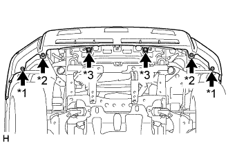
Install the 2 front engine mounting insulators with the 2 nuts.
- Torque:
- 46 N*m { 469 kgf*cm, 34 ft.*lbf }
-
-
INSTALL ENGINE HANGER
-
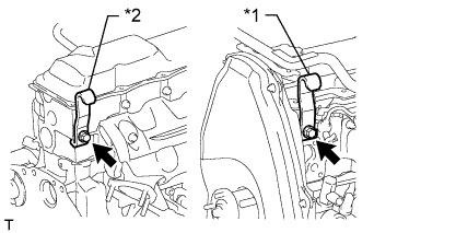
Text in Illustration *1 No. 1 Engine Hanger *2 No. 2 Engine Hanger Install an engine hanger to each location shown in the illustration.
Tech Tips
No. 1 Engine Hanger 12281-54080 No. 2 Engine Hanger 12282-54070 Bolt (No. 1 Engine Hanger) 90119-10736 Bolt (No. 2 Engine Hanger) 91622-61022 - Torque:
- for No. 1 Engine Hanger
- 59 N*m { 602 kgf*cm, 44 ft.*lbf }
- for No. 2 Engine Hanger
- 37 N*m { 377 kgf*cm, 27 ft.*lbf }
Note
Install the engine hangers with new bolts.
-
-
REMOVE ENGINE FROM ENGINE STAND
-
Attach an engine sling device and hang the engine with a chain block.
-
Lift the engine and remove it from the engine stand.
-
-
INSTALL ENGINE ASSEMBLY
-
Slowly lower the engine into the engine compartment.
-
Install the engine with the 4 bolts and 4 nuts.
- Torque:
- 40 N*m { 408 kgf*cm, 30 ft.*lbf }
Tech Tips
For RHD vehicles only:
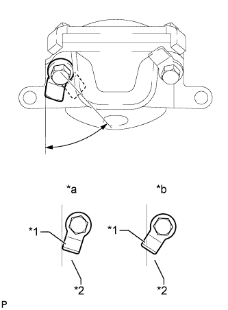
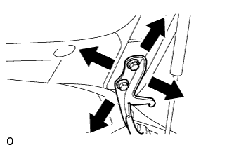
When tightening the nut closer to the rear of the vehicle for the engine mounting bracket on the right side, make sure that the claw (stopper) of the bolt does not protrude past the rear edge of the bracket.
Text in Illustration *1 Claw (Stopper) *2 Bracket *a Correct *b Incorrect -
Remove the 2 bolts and 2 engine hangers.
-
-
INSTALL FLYWHEEL HOUSING DUST SEAL
-
INSTALL REAR END PLATE
-
Install the rear end plate with the 2 bolts.
- Torque:
- 27 N*m { 275 kgf*cm, 20 ft.*lbf }
-
-
INSTALL FLYWHEEL SUB-ASSEMBLY
-
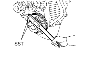
Using SST, hold the crankshaft.
- SST
- 09213-54015 ( 91651-60855 )
- 09330-00021
-
Clean the bolts and bolt holes.
-
Apply adhesive to 2 or 3 threads of each of the bolts.
Adhesive Toyota Genuine Adhesive 1324, Three Bond 1324 or equivalent -
Install the flywheel to the crankshaft.
-
Temporarily install the flywheel with the 8 bolts.
-
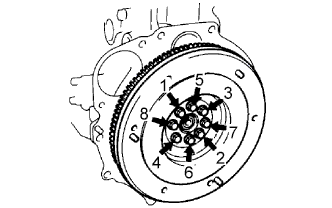
Tighten the 8 bolts uniformly in several steps in the order shown in the illustration.
- Torque:
- 123 N*m { 1249 kgf*cm, 90 ft.*lbf }
Note
Do not start the engine for at least 1 hour after installing.
-
-
INSTALL CLUTCH DISC ASSEMBLY
-
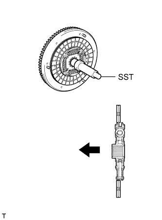
Insert SST into the clutch disc. Then insert SST (together with the clutch disc) into the flywheel to install the clutch disc.
- SST
- 09301-00110
Text in Illustration 
Flywheel Side Note
Be sure to install the clutch disc so that it is facing in the correct direction.
-
-
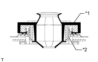
INSTALL CLUTCH COVER ASSEMBLY
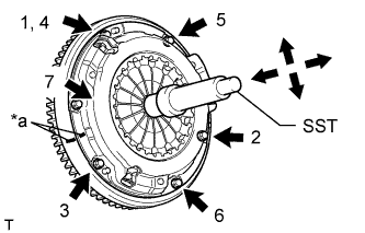
Text in Illustration *a Matchmark
-
Align the matchmarks on the clutch cover and flywheel.
-
Tighten the 6 bolts uniformly in the order shown in the illustration, starting with the bolt located near the knock pin on the top.
- SST
- 09301-00110
- Torque:
- 19 N*m { 194 kgf*cm, 14 ft.*lbf }
Tech Tips
Move SST up and down, and right and left lightly after checking that the clutch disc assembly is in the center, and then tighten the bolts.
-
-
INSTALL REAR NO. 1 ENGINE MOUNTING INSULATOR
-
Install the rear engine mounting insulator to the transmission with the 4 bolts.
Note
Perform this procedure when replacement of the engine mounting insulator is necessary.
- Torque:
- 65 N*m { 663 kgf*cm, 48 ft.*lbf }
-
-
INSTALL MANUAL TRANSMISSION ASSEMBLY
-
Install the manual transmission Click here.
-
-
INSTALL PROPELLER SHAFT ASSEMBLY
-
Align the matchmarks on the propeller shaft flange and differential flange.
-
Install the propeller shaft assembly with the 4 washer, 4 bolts and 4 nuts.
- Torque:
- 88 N*m { 899 kgf*cm, 65 ft.*lbf }
-
Align the matchmarks on the propeller shaft flange and transfer flange.
-
Install the propeller shaft assembly with the 4 washers and 4 nuts.
- Torque:
- 88 N*m { 899 kgf*cm, 65 ft.*lbf }
-
-
INSTALL FRONT PROPELLER SHAFT ASSEMBLY
-
Align the matchmarks on the yoke and differential flange.
-
Install the propeller shaft assembly with the 4 washers, 4 bolts and 4 nuts.
- Torque:
- 88 N*m { 899 kgf*cm, 65 ft.*lbf }
-
Align the matchmarks on the yoke and transfer flange.
-
Install the propeller shaft assembly with the 4 washers and 4 nuts.
- Torque:
- 88 N*m { 899 kgf*cm, 65 ft.*lbf }
-
-
INSTALL FRONT EXHAUST PIPE ASSEMBLY
-
Install a new gasket and the front exhaust pipe to the exhaust manifold with 3 new nuts.
- Torque:
- 54 N*m { 554 kgf*cm, 40 ft.*lbf }
-
Install the No. 1 exhaust pipe support bracket with the 2 bolts.
- Torque:
- 71 N*m { 724 kgf*cm, 52 ft.*lbf }
-
Install the clamp with the bolt.
- Torque:
- 19 N*m { 194 kgf*cm, 14 ft.*lbf }
-
-
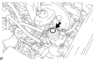
INSTALL OIL FILTER SUB-ASSEMBLY
-
Check and clean the oil filter installation surface.
-
Apply clean engine oil to the gasket of a new oil filter.
-
Install the oil filter and tighten it by hand until the gasket contacts the installation surface.
-
Using SST, tighten the oil filter. Choose from the following to further tighten the oil filter.
- SST
- 09228-44011
-

Using a torque wrench, tighten the oil filter.
- Torque:
- 17 N*m { 173 kgf*cm, 13 ft.*lbf }
-
Tighten the oil filter a 3/4 turn by hand or with a common wrench.
Text in Illustration 
3/4 turn
-
-
INSTALL STARTER ASSEMBLY
-
Install the starter assembly with the 2 bolts and nut.
- Torque:
- 68 N*m { 693 kgf*cm, 50 ft.*lbf }
-
Connect the starter wire with the nut.
- Torque:
- 9.8 N*m { 100 kgf*cm, 87 in.*lbf }
-
Install the terminal cap.
-
Connect the starter connector.
-
-
CONNECT CLUTCH RELEASE CYLINDER ASSEMBLY
-
Connect the release cylinder with the 2 bolts.
- Torque:
- 12 N*m { 120 kgf*cm, 9 ft.*lbf }
-
-
INSTALL VANE PUMP ASSEMBLY
-
Temporarily install the vane pump with the 2 bolts and nut.
-
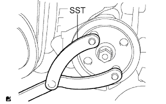
Install the pulley to the pump shaft.
-
Using SST, hold the pulley and install the nut.
- SST
- 09960-10010 ( 09962-01000, 09963-01000 )
- Torque:
- 43 N*m { 443 kgf*cm, 31 ft.*lbf }
-
-
CONNECT FUEL HOSE
-
Connect the 2 fuel hoses.
-
-
CONNECT HEATER WATER HOSE ASSEMBLY
-
Connect the 2 water hoses.
-
Install the heater water hose clamp with the bolt.
- Torque:
- 14 N*m { 138 kgf*cm, 10 ft.*lbf }
-
-
INSTALL WIRING HARNESS CLAMP BRACKET (for LHD)
-
Install the wiring harness clamp bracket with the bolt.
- Torque:
- 22 N*m { 219 kgf*cm, 16 ft.*lbf }
-
-
CONNECT ENGINE WIRE
-
Connect the ECM connector.
-
Text in Illustration *1 Grommet *2 Wire Harness Support Attach the grommet to the wire harness support.
-
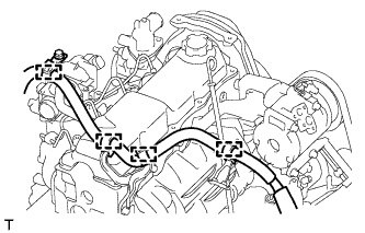
Pass the wire harness into the vehicle and install the wire harness support.
-
-
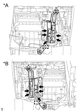
Text in Illustration *A for LHD *B for RHD Connect the 5 ECM connectors and attach the clamp.
-
for LHD:
Connect the 4 wire harness clamps.
-
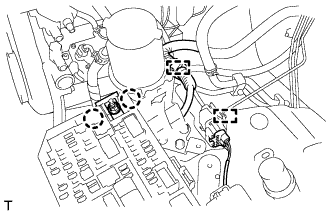
Attach the 2 clamps and connect the connector.
-
Attach the 2 claws and install the nut.
- Torque:
- 11 N*m { 112 kgf*cm, 8 ft.*lbf }
-
Install the No. 1 relay block cover.
-
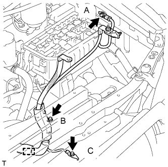
Attach the clamp and install the 3 bolts.
- Torque:
- for bolt A
- 8.5 N*m { 87 kgf*cm, 75 in.*lbf }
- for bolt B
- 8.0 N*m { 82 kgf*cm, 71 in.*lbf }
- for bolt C
- 19 N*m { 194 kgf*cm, 14 ft.*lbf }
-
-
INSTALL GLOVE COMPARTMENT DOOR ASSEMBLY
-
Install the glove compartment door Click here.
-
-
INSTALL GENERATOR ASSEMBLY
-
Temporarily install the generator with the 2 bolts.
-
Connect the vacuum pump oil outlet hose.
-
Install 2 new gaskets and the vacuum pump oil inlet hose with the union bolt.
- Torque:
- 14 N*m { 140 kgf*cm, 10 ft.*lbf }
-
Connect the vacuum pump hose.
-
Attach the vacuum pump oil inlet hose to the cord clip.
-
Install the generator wire with the nut.
- Torque:
- 9.8 N*m { 100 kgf*cm, 87 in.*lbf }
-
Install the terminal cap.
-
Connect the generator connector.
-
-
CONNECT COOLER COMPRESSOR ASSEMBLY
-
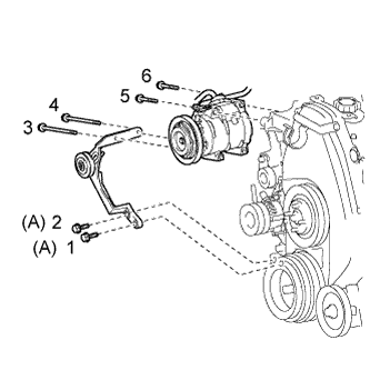
Temporarily install the cooler compressor with the 2 bolts.
-
Temporarily install the idle pulley bracket with the 4 bolts.
-
Tighten the 6 bolts in the sequence shown in the illustration.
- Torque:
- for bolt A
- 45 N*m { 459 kgf*cm, 33 ft.*lbf }
- except bolt A
- 25 N*m { 250 kgf*cm, 18 ft.*lbf }
-
Connect the wire harness with the bolt.
- Torque:
- 13 N*m { 131 kgf*cm, 9 ft.*lbf }
-
Connect the cooler compressor connector.
-
-
INSTALL INTAKE PIPE ASSEMBLY
-
Install the intake pipe with the 2 bolts.
- Torque:
- 18 N*m { 184 kgf*cm, 13 ft.*lbf }
-
Tighten the intake pipe clamp.
- Torque:
- 6.0 N*m { 61 kgf*cm, 53 in.*lbf }
-
-
INSTALL RADIATOR ASSEMBLY
-
Insert the tabs of the radiator support into the radiator service holes.
-
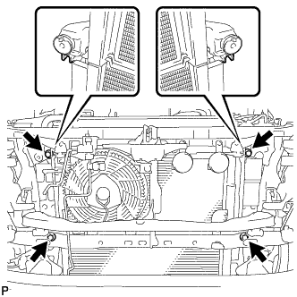
Install the radiator assembly with the 4 bolts to the radiator support.
- Torque:
- 18 N*m { 184 kgf*cm, 13 ft.*lbf }
-
-
INSTALL FAN SHROUD
-
Install the fan pulley to the water pump.
-
Install the shroud together with the coupling fan between the radiator and engine.
Note
Be careful not to damage the radiator core.
-
Temporarily install the fluid coupling fan to the fan pulley with the 4 nuts. Tighten the nuts as much as possible by hand.
-
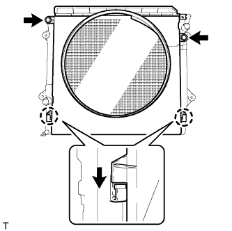
Attach the claws of the shroud as shown in the illustration.
-
Install the shroud with the 2 bolts.
- Torque:
- 5.0 N*m { 51 kgf*cm, 44 in.*lbf }
-
Install the fan and generator V belt and vane pump V belt Click here.
-
Tighten the 4 nuts of the fluid coupling fan.
- Torque:
- 19 N*m { 189 kgf*cm, 14 ft.*lbf }
-
-
INSTALL NO. 2 RADIATOR HOSE
-
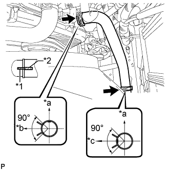
Text in Illustration *a Upper *b Front Side of Vehicle *c LH Side *1 Protrusion *2 Paint Mark Install the radiator hose.
Tech Tips
Position the hose clamps as shown in the illustration.
-
-
INSTALL NO. 1 RADIATOR HOSE
-
Install the hose clamp with the 2 nuts.
- Torque:
- 8.5 N*m { 87 kgf*cm, 75 in.*lbf }
-
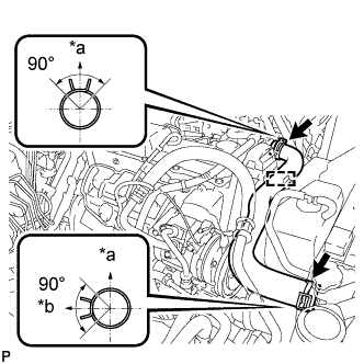
Text in Illustration *a Upper *b RH Side Install the radiator hose.
Tech Tips
Position the hose clamps as shown in the illustration.
-
-
INSTALL RADIATOR SIDE DEFLECTOR RH
-
Attach the 3 claws to the radiator support.
-
Install the radiator side deflector RH with the clip.
-
-
INSTALL RADIATOR SIDE DEFLECTOR LH
-
Attach the 3 claws to the radiator support.
-
Install the radiator side deflector LH with the clip.
-
-
INSTALL UPPER FRONT BUMPER RETAINER
-
Install the front bumper upper retainer with the 3 bolts.
- Torque:
- 8.0 N*m { 82 kgf*cm, 71 in.*lbf }
-
-
INSTALL FRONT BUMPER COVER
-
w/ TOYOTA Parking Assist-sensor System, w/ Fog Light:
Connect the 3 connectors.
-
w/ TOYOTA Parking Assist-sensor System, w/o Fog Light:
Connect the connector.
-
w/o TOYOTA Parking Assist-sensor System, w/ Fog Light:
Connect the 2 connectors.
-
w/ Headlight Cleaner System:
Connect the No. 1 headlight cleaner hose.
-
Attach the 16 claws to install the front bumper cover.
Note
Do not hold the middle of the front bumper cover, as it may become reformed.
-
Install the 4 clips.
-
Text in Illustration *1 Screw *2 Bolt A *3 Bolt B Install the 2 bolts labeled A and 2 bolts labeled B.
- Torque:
- bolt B
- 8.0 N*m { 82 kgf*cm, 71 in.*lbf }
-
Install the 2 screws.
-
Install the 2 screws.
Tech Tips
Use the same procedure for the screws on the other side.
-
-
INSTALL AIR CLEANER CASE ASSEMBLY
-
Install the air cleaner case with the 3 bolts.
- Torque:
- 12 N*m { 122 kgf*cm, 9 ft.*lbf }
-
-
INSTALL AIR CLEANER FILTER ELEMENT SUB-ASSEMBLY
-
INSTALL RESONATOR WITH AIR CLEANER CAP SUB-ASSEMBLY
-
Insert the hinge part of the air cleaner cap and hose into the air cleaner case, and then attach the 4 hook clamps.
-
Connect the air cleaner cap sub-assembly with the clamp.
- Torque:
- 5.0 N*m { 51 kgf*cm, 44 in.*lbf }
-
Attach the wire harness clamp.
-
Connect the 2 clamps and connector.
-
-
INSTALL NO. 1 FRONT FENDER APRON TO FRAME SEAL LH
-
Install the No. 1 front fender apron to frame seal with the 5 clips.
-
-
INSTALL FRONT FENDER APRON SEAL LH
-
Install the front fender apron seal with the 5 clips.
-
-
INSTALL NO. 1 FRONT FENDER APRON TO FRAME SEAL RH
-
Install the No. 1 front fender apron to frame seal with the 5 clips.
-
-
INSTALL FRONT FENDER APRON SEAL RH
-
Install the front fender apron seal with the 4 clips.
-
-
INSTALL REAR ENGINE UNDER COVER ASSEMBLY
-
Install the rear engine under cover with the 4 bolts.
- Torque:
- 29 N*m { 296 kgf*cm, 21 ft.*lbf }
-
-
INSTALL TRANSMISSION UNDER COVER
-
Install the transmission under cover with the 2 bolts.
- Torque:
- 29 N*m { 296 kgf*cm, 21 ft.*lbf }
-
-
INSTALL NO. 1 ENGINE UNDER COVER SUB-ASSEMBLY
-
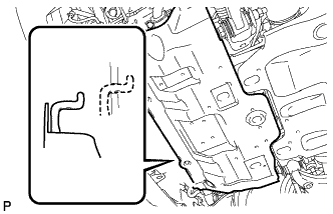
Hook the engine under cover to the vehicle body as shown in the illustration.
-
Install the 4 bolts.
- Torque:
- 29 N*m { 296 kgf*cm, 21 ft.*lbf }
-
-
INSTALL FRONT BUMPER COVER LOWER
-
Install the front bumper cover lower with the 5 bolts and clip.
- Torque:
- 8.0 N*m { 82 kgf*cm, 71 in.*lbf }
-
-
INSTALL UPPER RADIATOR SUPPORT SEAL
-
Install the upper radiator support seal with the 13 clips.
-
-
INSTALL COWL TOP VENTILATOR LOUVER SUB-ASSEMBLY
-
Install the cowl top ventilator louver Click here.
-
-
INSTALL HOOD SUB-ASSEMBLY
-
Install the hood with the 8 bolts.
- Torque:
- for bolt A
- 13 N*m { 133 kgf*cm, 10 ft.*lbf }
- for bolt B
- 18 N*m { 184 kgf*cm, 13 ft.*lbf }
Text in Illustration Bolt A Bolt B -
Connect the washer nozzle hose.
-
-
ADJUST HOOD SUB-ASSEMBLY
-
Adjust the hood position.
-
Loosen the 4 hinge bolts on the hood.
-
Move the hood and adjust the clearance between the hood and front fender.
-
Tighten the 4 hinge bolts on the hood.
- Torque:
- 13 N*m { 133 kgf*cm, 10 ft.*lbf }
-
-
Adjust the height of the front end of the hood using the cushion rubbers.
-
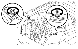
Adjust the 2 cushion rubbers so that the heights of the hood and fender are aligned.
Tech Tips
Raise or lower the front end of the hood by turning the 2 cushion rubbers.
-
-
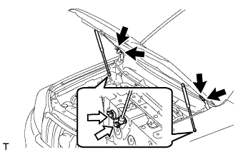
Adjust the hood lock.
-
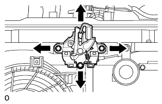
Loosen the 3 bolts.
-
Adjust the hood lock and tighten the 3 bolts.
- Torque:
- 7.5 N*m { 76 kgf*cm, 66 in.*lbf }
-
Check that the striker can smoothly engage with the hood lock.
-
-
-
INSTALL BATTERY TRAY
-
INSTALL BATTERY
-
INSTALL BATTERY HOLD DOWN CLAMP
-
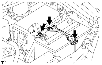
Install the battery hold down clamp with the 2 nuts.
- Torque:
- 6.0 N*m { 61 kgf*cm, 53 in.*lbf }
-
Connect the engine wire with the nut labeled A.
- Torque:
- 7.5 N*m { 76 kgf*cm, 66 in.*lbf }
-
-
CONNECT CABLE TO NEGATIVE BATTERY TERMINAL
Note
When disconnecting the cable, some systems need to be initialized after the cable is reconnected Click here.
-
ADD ENGINE OIL
-
Add fresh engine oil.
Standard Engine Oil Oil Grade Oil Viscosity (SAE) API CF-4 or CF 10W-30 Standard Capacity Item Specified Condition Drain and refill without oil filter change 6.0 liters (6.3 US qts, 5.3 Imp. qts) Drain and refill with oil filter change 6.9 liters (7.3 US qts, 6.1 Imp. qts) Dry fill 7.6 liters (8.0 US qts, 6.7 Imp. qts) -
Install the oil filler cap.
-
-
ADD ENGINE COOLANT
-
Tighten the radiator drain cock plug by hand.
-
Tighten the cylinder block drain cock plug.
- Torque:
- 13 N*m { 130 kgf*cm, 9 ft.*lbf }
-
Slowly fill the system with engine coolant.
Standard capacity 8.6 liters (9.0 US qts, 7.6 Imp. qts) Note
Do not substitute plain water for engine coolant.
Tech Tips
-
Use only Toyota Super Long Life Coolant or similar high quality ethylene glycol based non-silicate, non-amine, non-nitrite, and non-borate coolant with long-life hybrid organic acid technology (coolant with long-life hybrid organic acid technology consists of a combination of low phosphates and organic acids.)
-
New Toyota vehicles are filled with Toyota Super Long Life Coolant. When replacing the coolant, Toyota Super Long Life Coolant (color is pink, premixed ethylene glycol concentration is approximately 50% and freezing temperature is -35°C (-31°F)) is recommended
-
-
Slowly pour coolant into the radiator reservoir until it reaches the Full line.
-
Install the reservoir cap.
-
Press the No. 1 and No. 2 radiator hoses several times by hand, and then check the coolant level. If the coolant level is low, add coolant.
-
Install the radiator cap.
-
Start the engine and warm it up until the thermostat opens.
Tech Tips
The thermostat opening timing can be confirmed by pressing the No. 2 radiator hose by hand and checking when the engine coolant starts to flow inside the hose.
-
Maintain the engine speed at 2000 to 2500 rpm.
Note
-
Make sure that the radiator reservoir still has some coolant in it.
-
Pay attention to the needle of the water temperature meter. Make sure that the needle does not show an abnormally high temperature.
-
If there is not enough coolant, the engine may burn out or overheat.
-
Immediately after starting the engine, if the radiator reservoir does not have any coolant, perform the following: 1) stop the engine, 2) wait until the coolant has cooled down, and 3) add coolant until the coolant is filled to the F line.
-
Run the engine at 2000 rpm until the coolant level has stabilized.
-
-
Press the No. 1 and No. 2 radiator hoses several times by hand to bleed air.
CAUTION:
-
Wear protective gloves. Heat areas on the parts may injure your hands.
-
Be careful as the radiator hoses are hot.
-
Keep your hands away from the fan.
-
-
Stop the engine, and wait until the engine coolant cools down to ambient temperature.
CAUTION:
Do not remove the radiator cap while the engine and radiator are still hot. Pressurized, hot engine coolant and steam may be released and cause serious burns.
-
Check that the coolant level is between the Full and Low lines.
If the coolant level is below the Low line, repeat all of the steps above.
If the coolant level is above the Full line, drain coolant so that the coolant level is between the Full and Low lines.
-
-
TIGHTEN FUEL TANK CAP ASSEMBLY
-
BLEED AIR FROM FUEL SYSTEM
-
Using the hand pump mounted on the fuel filter cap, bleed the air from the fuel system. Continue pumping until the pump resistance increases.
-
-
INSPECT FOR FUEL LEAK
-
Check that there are no fuel leaks anywhere in the fuel system after performing maintenance.
Tech Tips
When checking for fuel leaks, make sure that there is pressure in the fuel line.
-
-
INSPECT FOR ENGINE OIL LEAK
-
Start the engine. Make sure that there are no oil leaks from the areas that were worked on.
-
-
INSPECT FOR COOLANT LEAK
CAUTION:
To avoid being burned, do not remove the radiator reservoir cap while the engine and radiator are still hot. Thermal expansion may cause hot engine coolant and steam to blow out from the radiator.
-
Fill the radiator with coolant and attach a radiator cap tester to the radiator.
-
Warm up the engine.
-
Using a radiator cap tester, increase the pressure inside the radiator to 123 kPa (1.3 kgf/cm2, 18 psi), and check that the pressure does not drop.
If the pressure drops, check the hoses, radiator or water pump for leaks. If no external leaks are found, check the heater core, cylinder block, and cylinder head.
-
-
ADD MANUAL TRANSMISSION OIL
-
INSPECT FOR GAS LEAK
-
If gas is leaking, tighten the areas necessary to stop the leak. Replace damaged parts as necessary.
-
-
INSPECT ENGINE IDLE SPEED
-
Warm up the engine.
-
When using the intelligent tester:
-
Connect the intelligent tester to the DLC3.
Idle speed 720 to 820 rpm Note
-
Turn all the electrical systems and the A/C off.
-
When checking the idling speed, the shift lever should be in neutral.
Tech Tips
Refer to the intelligent tester operator's manual for further details.
-
-
-
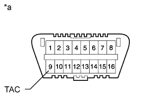
Text in Illustration *a Front View of DLC3 When not using an intelligent tester:
-
Using SST, connect the tachometer test probe to terminal 9 (TAC) of the DLC3.
- SST
- 09843-18040
-
Check the idle speed.
Standard idle speed 720 to 820 rpm Note
-
Turn all the electrical systems and the A/C off.
-
When checking the idling speed, the shift lever should be in neutral.
-
Confirm the terminal number before connecting them. Connecting the wrong terminal can be damage the engine.
-
-
-
-
INSPECT MAXIMUM ENGINE SPEED
-
Start the engine.
-
Fully depress the accelerator pedal.
-
Check the maximum speed.
Maximum engine speed 4850 to 4950 rpm
-