TIMING BELT INSTALLATION

-
INSTALL NO. 1 TIMING BELT IDLER SUB-ASSEMBLY
-
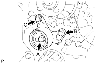
Install the No. 1 belt idler with the 3 bolts.
- Torque:
- for bolt A
- 44 N*m { 449 kgf*cm, 32 ft.*lbf }
- for bolt B, C
- 19 N*m { 195 kgf*cm, 14 ft.*lbf }
Tech Tips
-
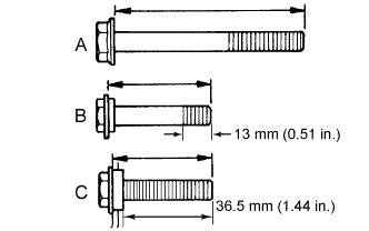
The bolt lengths for bolt A, B and C as follows.
-
Bolt C is combined with the No. 1 timing belt idler.
Standard Bolt Item Length A 76.5 mm (3.01 in.) B 42.9 mm (1.69 in.) C 41.3 mm (1.63 in.)
-
-
SET NO. 1 CYLINDER TO TDC/COMPRESSION
-
Text in Illustration *1 Timing Mark 
Turn Using the crankshaft pulley bolt, align the groove of the crankshaft pulley with the timing pointer by turning the crankshaft clockwise.
Note
Do not turn the crankshaft pulley counterclockwise.
-
Set the timing and drive pulleys at each position.
Note
-
Make sure the engine is cold.
-
When turning the crankshaft or camshaft, the valve heads will hit against the piston top. Do not turn them more than necessary.
-
-
-
INSTALL TIMING BELT
Tech Tips
If reusing the timing belt, align the points marked during removal, and install the timing belt with the arrow pointing in the direction the belt moves when the engine is running.
-
Remove any oil or water on each pulley, and keep them clean.
-
Install the timing belt to the crankshaft timing and timing belt idlers.
-
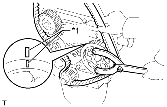
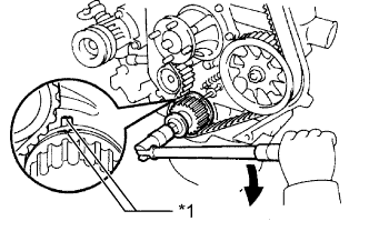
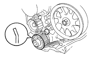
Text in Illustration *1 Timing Mark Using SST, slightly turn the injection pump drive pulley clockwise. Install the timing belt to the pulley, and align the timing marks of the drive pulley and timing belt case.
- SST
- 09960-10010 ( 09962-01000, 09963-01000 )
-
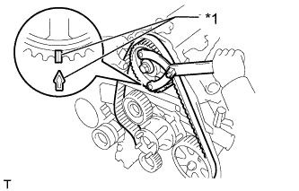
Text in Illustration *1 Timing Mark Using SST, slightly turn the camshaft timing pulley clockwise. Install the timing belt to the timing pulley, and align the timing marks of the timing pulley and timing belt case.
- SST
- 09960-10010 ( 09962-01000, 09963-01000 )
-
Check that the timing belt has tension between the injection pump drive and camshaft timing pulleys.
-
Install the timing belt to the No. 1 timing belt idler.
-
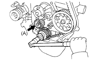
Loosen the No. 1 timing belt idler bolt (A), and stretch the timing belt.
-
Slowly turn the crankshaft pulley.
Note
Always turn the crankshaft clockwise.
-
Tighten the No. 1 timing belt idler bolt.
- Torque:
- 44 N*m { 449 kgf*cm, 33 ft.*lbf }
-
-
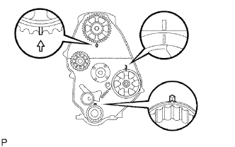
CHECK NO. 1 CYLINDER TO TDC/COMPRESSION
-
Slowly turn the crankshaft pulley 2 revolutions from TDC to TDC.
Note
Always turn the crankshaft clockwise.
-
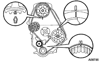
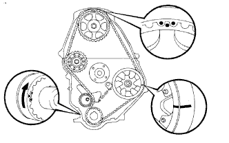
Check that the timing marks for each pulley align as shown in the illustration.
If the timing marks do not align, remove the timing belt and reinstall it.
-
-
INSTALL TIMING BELT GUIDE
-
Install the timing belt guide with the cup side facing outward.
-
-
INSTALL TIMING BELT COVER
-
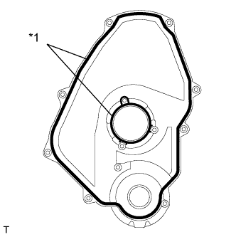
Text in Illustration *1 Gasket Install 2 new gaskets to the timing belt cover.
-
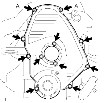
Install the timing belt cover with the 11 bolts and washers.
- Torque:
- for bolt A
- 8.5 N*m { 85 kgf*cm, 75 ft.*lbf }
- except bolt A
- 11 N*m { 107 kgf*cm, 8 ft.*lbf }
-
-
INSTALL IDLE PULLEY ASSEMBLY
-
Install the idle pulley bracket with the 2 bolts.
- Torque:
- 29 N*m { 300 kgf*cm, 22 ft.*lbf }
-
-
INSTALL CRANKSHAFT PULLEY
-
Align the key groove of the pulley with the pulley set key, and slide the pulley onto the crankshaft to install it.
-
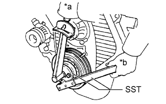
Text in Illustration *a Turn *b Hold Using SST, install the pulley bolt.
- SST
- 09213-54015 ( 91651-60855 )
- 09330-00021
- Torque:
- 235 N*m { 2396 kgf*cm, 173 ft.*lbf }
-
-
INSTALL VANE PUMP DRIVE PULLEY
-
Install the vane pump drive pulley and cooler compressor drive pulley with the 4 bolts.
- Torque:
- 19 N*m { 194 kgf*cm, 14 ft.*lbf }
-
-
INSTALL FAN SHROUD
-
Install the fan shroud Click here.
-
-
CONNECT CABLE TO NEGATIVE BATTERY TERMINAL
Note
When disconnecting the cable, some systems need to be initialized after the cable is reconnected Click here.
-
INSPECT ENGINE IDLE SPEED
-
Warm up the engine.
-
When using the intelligent tester:
-
Connect the intelligent tester to the DLC3.
Idle speed 720 to 820 rpm Note
-
Turn all the electrical systems and the A/C off.
-
When checking the idling speed, the shift lever should be in neutral.
Tech Tips
Refer to the intelligent tester operator's manual for further details.
-
-
-
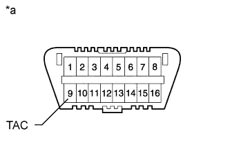
Text in Illustration *a Front View of DLC3 When not using an intelligent tester:
-
Using SST, connect the tachometer test probe to terminal 9 (TAC) of the DLC3.
- SST
- 09843-18040
-
Check the idle speed.
Standard idle speed 720 to 820 rpm Note
-
Turn all the electrical systems and the A/C off.
-
When checking the idling speed, the shift lever should be in neutral.
-
Confirm the terminal number before connecting them. Connecting the wrong terminal can be damage the engine.
-
-
-
-
INSPECT MAXIMUM ENGINE SPEED
-
Start the engine.
-
Fully depress the accelerator pedal.
-
Check the maximum speed.
Maximum engine speed 4850 to 4950 rpm
-