VALVE CLEARANCE ADJUSTMENT

-
REMOVE RESONATOR WITH AIR CLEANER CAP SUB-ASSEMBLY
-
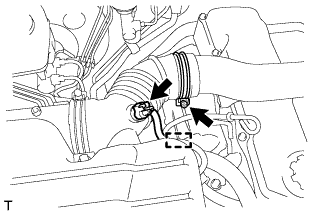
Disconnect the sensor connector.
-
Detach the wire harness clamp.
-
Loosen the hose clamp and remove the resonator with air cleaner cap.
-
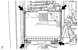
Detach the 4 hook clamps, and then remove the air cleaner cap and resonator with air cleaner cap.
-
-
REMOVE INTAKE AIR CONNECTOR SUB-ASSEMBLY
-
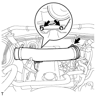
Loosen the hose clamp and remove the 2 bolts and intake pipe.
-
-
REMOVE CYLINDER HEAD COVER SUB-ASSEMBLY
-
Remove the 9 bolts, nut, cylinder head cover and gasket.
-
-
SET NO. 1 CYLINDER TO TDC/COMPRESSION
-
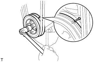
Turn the crankshaft pulley and align its groove with the timing pointer.
-
Check that the valve lifters for the No. 1 cylinder are loose and the valve lifters for the No. 4 cylinder are tight.
If not, turn the crankshaft 1 revolution (360°) and align the mark as above.
-
-
INSPECT VALVE CLEARANCE
-
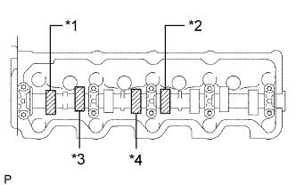
Text in Illustration *1 No. 1 EX *2 No. 3 EX *3 No. 1 IN *4 No. 2 IN Check only the valves indicated in the illustration.
-
Using a feeler gauge, measure the clearance between the valve lifter and camshaft.
Standard Valve Clearance (Cold) Item Specified Condition Intake 0.20 to 0.30 mm (0.00787 to 0.0118 in.) Exhaust 0.40 to 0.50 mm (0.0158 to 0.0197 in.) -
Record the out-of-specification valve clearance measurements. They will be used later to determine the required replacement adjusting shim.
-
-
Turn the crankshaft 1 revolution (360°) and align the mark as above.
-
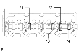
Text in Illustration *1 No. 2 EX *2 No. 4 EX *3 No. 3 IN *4 No. 4 IN Check only the valves indicated in the illustration.
-
Using a feeler gauge, measure the clearance between the valve lifter and camshaft.
Standard Valve Clearance (Cold) Item Specified Condition Intake 0.20 to 0.30 mm (0.00787 to 0.0118 in.) Exhaust 0.40 to 0.50 mm (0.0158 to 0.0197 in.) -
Record the out-of-specification valve clearance measurements. They will be used later to determine the required replacement adjusting shim.
-
-
-
ADJUST VALVE CLEARANCE
-
Remove the adjusting shim.
-
Turn the crankshaft so that the cam lobe of the camshaft on the valve being adjusted points upward.
-
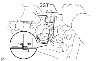
Using SST, press down the valve lifter.
- SST
- 09248-64011
-
Position the notch of the valve lifter so that it faces the exhaust manifold side.
-
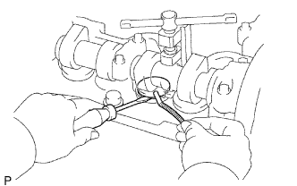
Remove the adjusting shim with a screwdriver and magnet hand.
-
-
Determine the replacement adjusting shim size according to the formula and charts below.
-
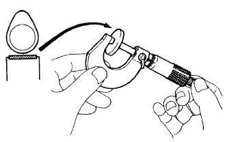
Using a micrometer, measure the thickness of the removed shim.
-
Calculate the thickness of a new shim so that the valve clearance comes within the specified value.
T = Thickness of removed shim
A = Measured valve clearance
N = Thickness of new shim
Intake N = T + (A - 0.25 mm (0.00984 in.)) Exhaust N = T + (A - 0.45 mm (0.0177 in.)) -
Select a new shim with a thickness as close as possible to the calculated value.
Tech Tips
Shims are available in 17 sizes in increments of 0.05 mm (0.00197 in.), from 2.50 mm (0.0984 in.) to 3.30 mm (0.130 in.).
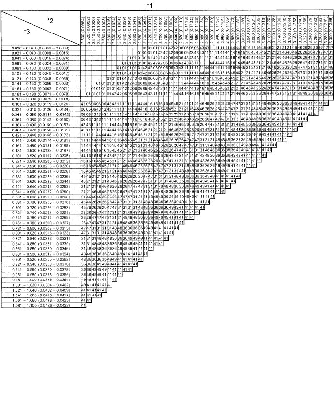
Text in Illustration *1 Adjusting Shim Selection Chart (Intake) *2 Removed shim thickness mm (in.) *3 Measure clearance mm (in.) - - New Shim Thickness mm (in.) Shim No. Thickness Shim No. Thickness 01 2.50 (0.0984) 46 2.95 (0.116) 42 2.55 (0.100) 26 3.00 (0.118) 06 2.60 (0.102) 47 3.05 (0.120) 43 2.65 (0.104) 31 3.10 (0.122) 11 2.70 (0.106) 48 3.15 (0.124) 44 2.75 (0.108) 36 3.20 (0.126) 16 2.80 (0.110) 49 3.25 (0.128) 45 2.85 (0.112) 41 3.30 (0.130) 21 2.90 (0.114) Intake valve clearance (Cold) 0.20 to 0.30 mm (0.00787 to 0.0118 in.) EXAMPLE:
A 2.80 mm (0.110 in.) shim is installed and the measured clearance is 0.350 mm (0.0138 in.). Replace the 2.80 mm (0.110 in.) shim with a No. 21 shim.
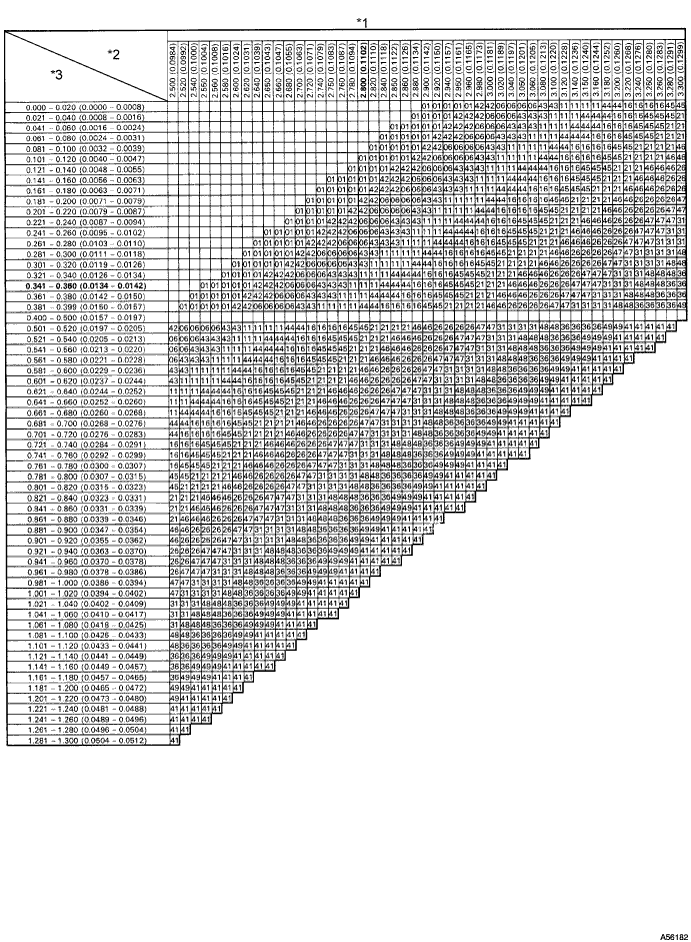
Text in Illustration *1 Adjusting Shim Selection Chart (Exhaust) *2 Removed Shim Thickness mm (in.) *3 Measure Clearance mm (in.) - - New Shim Thickness mm (in.) Shim No. Thickness Shim No. Thickness 01 2.50 (0.0984) 46 2.95 (0.116) 42 2.55 (0.100) 26 3.00 (0.118) 06 2.60 (0.102) 47 3.05 (0.120) 43 2.65 (0.104) 31 3.10 (0.122) 11 2.70 (0.106) 48 3.15 (0.124) 44 2.75 (0.108) 36 3.20 (0.126) 16 2.80 (0.110) 49 3.25 (0.128) 45 2.85 (0.112) 41 3.30 (0.130) 21 2.90 (0.114) Exhaust valve clearance (Cold) 0.40 to 0.50 mm (0.0157 to 0.0196 in.) EXAMPLE:
A 2.80 mm (0.110 in.) shim is installed and the measured clearance is 0.350 mm (0.0138 in.). Replace the 2.80 mm (0.110 in.) shim with a No. 11 shim.
-
-
Install a new adjusting shim.
-
Install a new adjusting shim to the valve lifter.
-
Remove SST.
-
-
Recheck valve clearance.
-
-
INSTALL CYLINDER HEAD COVER SUB-ASSEMBLY
-
Remove any old packing (FIPG material).
-
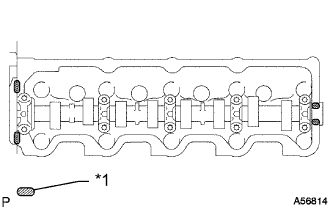
Text in Illustration *1 Seal Packing Apply seal packing to the cylinder head as shown in the illustration.
Seal packing Toyota Genuine Seal Packing Black, Three Bond 1207B or equivalent -
Install the gasket to the cylinder head cover.
-
Install the cylinder head cover with the 9 bolts and nut. Uniformly tighten the bolts and nut in several steps.
- Torque:
- 12 N*m { 122 kgf*cm, 9 ft.*lbf }
-
-
INSTALL INTAKE AIR CONNECTOR SUB-ASSEMBLY
-
Install the intake pipe with the 2 bolts.
- Torque:
- 18 N*m { 184 kgf*cm, 13 ft.*lbf }
-
Tighten the intake pipe clamp.
- Torque:
- 6.0 N*m { 61 kgf*cm, 53 in.*lbf }
-
-
INSTALL RESONATOR WITH AIR CLEANER CAP SUB-ASSEMBLY
-
Insert the hinge part of the air cleaner cap and hose into the air cleaner case, and then attach the 4 hook clamps.
-
Connect the air cleaner cap sub-assembly with the clamp.
- Torque:
- 5.0 N*m { 51 kgf*cm, 44 in.*lbf }
-
Attach the wire harness clamp.
-
Connect the 2 clamps and connector.
-
-
INSPECT ENGINE IDLE SPEED
-
Warm up the engine.
-
When using the intelligent tester:
-
Connect the intelligent tester to the DLC3.
Idle speed 720 to 820 rpm Note
-
Turn all the electrical systems and the A/C off.
-
When checking the idling speed, the shift lever should be in neutral.
Tech Tips
Refer to the intelligent tester operator's manual for further details.
-
-
-
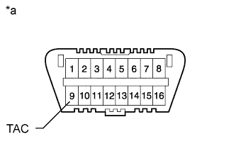
Text in Illustration *a Front View of DLC3 When not using an intelligent tester:
-
Using SST, connect the tachometer test probe to terminal 9 (TAC) of the DLC3.
- SST
- 09843-18040
-
Check the idle speed.
Standard idle speed 720 to 820 rpm Note
-
Turn all the electrical systems and the A/C off.
-
When checking the idling speed, the shift lever should be in neutral.
-
Confirm the terminal number before connecting them. Connecting the wrong terminal can be damage the engine.
-
-
-
-
INSPECT MAXIMUM ENGINE SPEED
-
Start the engine.
-
Fully depress the accelerator pedal.
-
Check the maximum speed.
Maximum engine speed 4850 to 4950 rpm
-