CYLINDER BLOCK REASSEMBLY

-
INSTALL STUD BOLT
Tech Tips
If a stud bolt is deformed or the threads are damaged, replace it.
-
Install the stud bolts.
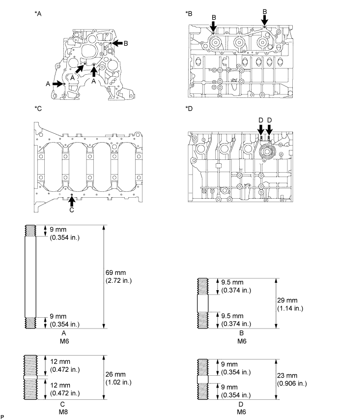
Text in Illustration *A for Front Side *B for Left Side *C for Oil Pan Side *D for Right Side
-
-
INSTALL NO. 1 OIL NOZZLE SUB-ASSEMBLY
-
Align the pin of the No. 1 oil nozzle with the pin hole of the cylinder block.
-
Install the 4 No. 1 oil nozzles with the 4 check valves.
- Torque:
- 26 N*m { 265 kgf*cm, 19 ft.*lbf }
-
-
INSTALL PISTON WITH PIN SUB-ASSEMBLY
-
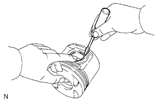
Using a small screwdriver, install a new snap ring on one side of the piston pin hole.
-
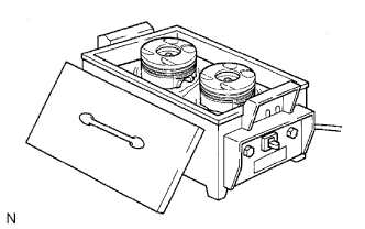
Gradually heat the piston to approximately 80°C (176°F).
-
Coat the piston pin with engine oil.
-
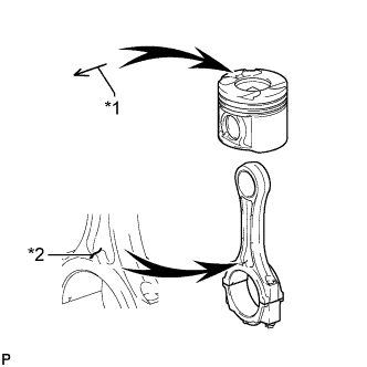
Text in Illustration *1 Front Mark (Arrow) *2 Front Mark (Protrusion) Align the front marks of the piston and connecting rod, connect the connecting rod to the piston, and then push in the piston pin with your thumb.
-
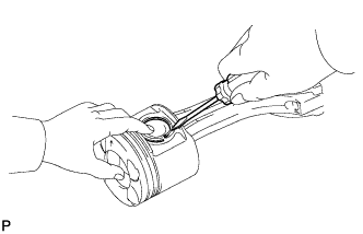
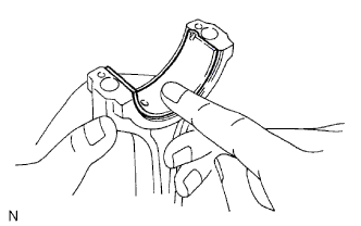
Check the fit between the piston and piston pin. Try to move the piston back and forth on the piston pin.
-
Using a small screwdriver, install a new snap ring on the other side of the piston pin hole.
-
-
INSTALL PISTON RING SET
-
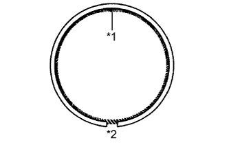
Text in Illustration *1 Coil Joint *2 Oil Ring End Install the coil and oil ring by hand.
Tech Tips
Make sure the end gap of the oil ring and the coil joint are on opposite sides.
-
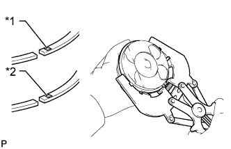
Text in Illustration *1 No. 1 *2 No. 2 Using a piston ring expander, install the No. 1 and No. 2 piston rings with the code marks facing upward.
Code Mark Ring Code Mark No. 1 w/ EGR Cooler without DPF NAA Other NAC No. 2 w/ EGR Cooler without DPF N Other KD1 -
Text in Illustration *1 No. 1 Piston Ring *2 Oil Ring *3 Coil *4 No. 2 Piston Ring *5 Front Mark (Arrow) Position the piston rings so that the ring ends are as shown in the illustration.
Note
Do not align the ring ends.
-
-
INSTALL CRANKSHAFT BEARING
Tech Tips
Upper bearings have an oil groove and oil hole. Lower bearings do not.
-
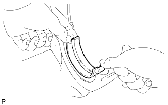
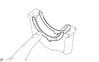
Align the bearing claw with the claw groove of the cylinder block and push in the 5 upper bearings.
-
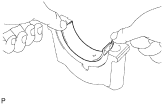
Align the bearing claw with the claw groove of the crankshaft bearing cap and push in the 5 lower bearings.
-
-
INSTALL CRANKSHAFT
-
Place the crankshaft on the cylinder block.
-
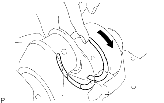
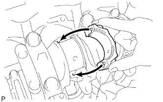
Push the crankshaft in one direction and install one thrust washer to the No. 5 journal position with the oil groove facing outward.
-
Push the crankshaft in the opposite direction and install the other thrust washer to the No. 5 journal position with the oil groove facing outward.
-
Install the 2 thrust washers to the No. 5 bearing cap with the grooves facing outward.
-
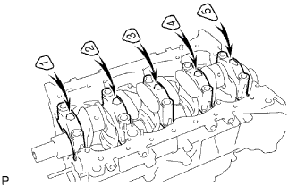
Install the 5 crankshaft bearing caps to their proper locations.
-
Install the crankshaft bearing cap bolts.
Tech Tips
-
The crankshaft bearing cap bolts are tightened in 2 progressive steps.
-
If a crankshaft bearing cap bolt is broken or deformed, replace it.
-
Apply a light coat of engine oil to the threads and under the bolt heads of the crankshaft bearing cap bolts.
-
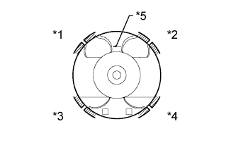
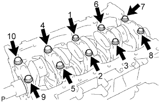
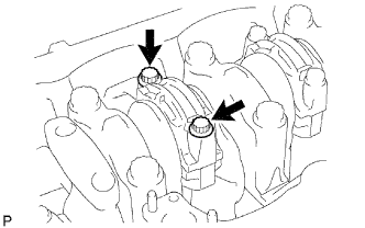
Install and uniformly tighten the 10 bolts of the crankshaft bearing caps in several passes in the sequence shown in the illustration.
- Torque:
- 50 N*m { 510 kgf*cm, 37 ft.*lbf }
If any one of the bearing cap bolts does not meet the torque specification, replace the bearing cap bolt.
-
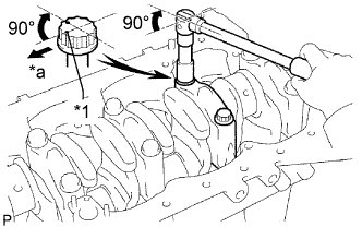
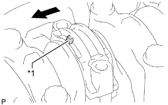
Text in Illustration *1 Painted Mark *a Front Mark the front of each crankshaft bearing cap bolt with paint.
-
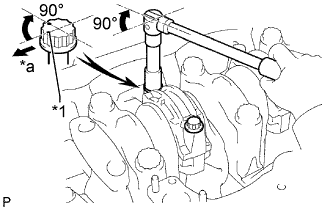
Tighten the crankshaft bearing cap bolts by 90° in the numerical order shown in the previous illustration.
-
Check that the painted marks are now at a 90° angle to the front.
-
-
Check that the crankshaft turns smoothly.
-
Check the crankshaft thrust clearance.
-
-
INSTALL CONNECTING ROD BEARING
-
Align the bearing claw with the groove of the connecting rod or connecting rod cap.
-
Install the bearings to the connecting rod and connecting rod cap.
-
-
INSPECT CRANKSHAFT THRUST CLEARANCE
-
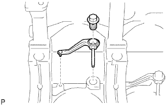
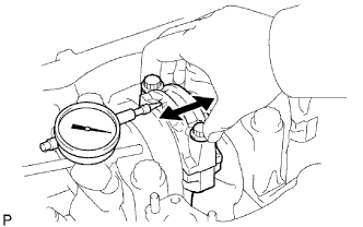
Using a dial indicator, measure the thrust clearance while prying the crankshaft back and forth with a screwdriver.
Standard thrust clearance 0.04 to 0.24 mm (0.00157 to 0.00945 in.) Maximum thrust clearance 0.3 mm (0.0118 in.) If the thrust clearance is more than the maximum, replace the thrust washers as a set.
Standard Thrust Washer Thickness Item Specified Condition STD 2.430 to 2.480 mm (0.0957 to 0.0976 in.) O/S 0.125 2.555 to 2.605 mm (0.1005 to 0.1025 in.) O/S 0.250 2.680 to 2.730 mm (0.1055 to 0.1074 in.)
-
-
INSTALL PISTON AND CONNECTING ROD
-
Apply engine oil to the cylinder walls, pistons and the surfaces of the connecting rod bearings.
-
Check the positions of the piston ring ends.
-
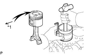
Text in Illustration *1 Front Mark (Arrow) Using a piston ring compressor, push the correctly numbered piston and connecting rod assembly into the cylinder with the front mark of the piston facing forward.
-
Place the connecting rod cap on the connecting rod.
-
Match each numbered connecting rod cap with the correct connecting rod.
-
Align the pins of the connecting rod cap with the pin holes of the connecting rod and install the connecting rod cap.
-
Text in Illustration *1 Front Mark (Protrusion) 
Front Check that the front mark of the connecting rod cap is facing forward.
-
-
Install the connecting rod cap bolts.
Tech Tips
-
The connecting rod cap bolts are tightened in 2 progressive steps.
-
If any connecting rod bolt is broken or deformed, replace it.
-
Apply a light coat of engine oil to the threads and under the heads of the connecting rod cap bolts.
-
Install and alternately tighten the bolts of the connecting rod cap in several passes.
- Torque:
- 35 N*m { 357 kgf*cm, 26 ft.*lbf }
Tech Tips
If any one of the connecting rod cap bolts does not meet the torque specification, replace the cap bolt.
-
Text in Illustration *1 Painted Mark *a Front Mark the front of each connecting rod cap bolt with paint.
-
Tighten the connecting rod cap bolts by 90° as shown in the illustration.
-
Check that the painted marks are now at a 90° angle to the front.
-
-
Check that the crankshaft turns smoothly.
-
-
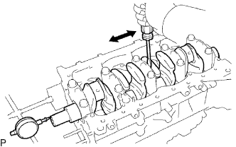
INSPECT CONNECTING ROD THRUST CLEARANCE
-
Using a dial indicator, measure the thrust clearance while moving the connecting rod back and forth.
Standard thrust clearance 0.1 to 0.3 mm (0.00394 to 0.0118 in.) Maximum thrust clearance 0.4 mm (0.0157 in.) If the thrust clearance is more than the maximum, replace the connecting rod assembly. If necessary, replace the crankshaft.
-
-
INSTALL CYLINDER BLOCK OIL ORIFICE