CYLINDER HEAD REPLACEMENT

-
REPLACE INTAKE VALVE GUIDE BUSH
-
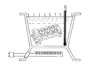
Gradually heat the cylinder head to approximately 80 to 100°C (176 to 212°F).
-
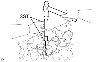
Using SST and a hammer, tap out the valve guide bush.
- SST
- 09201-10000 ( 09201-01060 )
- 09950-70010 ( 09951-07100 )
-
Using a caliper gauge, measure the bush bore diameter of the cylinder head.
-
Select a new guide bush.
New Guide Bush Item Specified Condition Bush bore diameter 10.985 to 11.006 mm (0.432 to 0.433 in.) 11.035 to 11.056 mm (0.434 to 0.435 in.) Use bush STD O/S 0.05 If the bush bore diameter of the cylinder head is more than 11.006 mm (0.433 in.), machine the bush bore diameter to between 11.035 and 11.056 mm (0.434 and 0.435 in.).
If the bush bore diameter of the cylinder head is more than 11.056 mm (0.435 in.), replace the cylinder head.
-
Gradually heat the cylinder head to approximately 80 to 100°C (176 to 212°F).
-
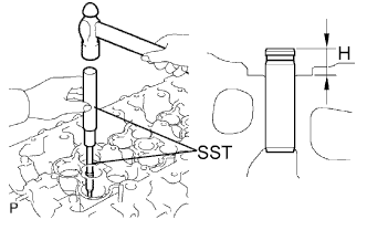
Using SST and a hammer, tap in a new guide bush to the specified protrusion height.
- SST
- 09201-10000 ( 09201-01060 )
- 09950-70010 ( 09951-07100 )
Standard protrusion height (H) 10.3 to 10.7 mm (0.406 to 0.421 in.) -
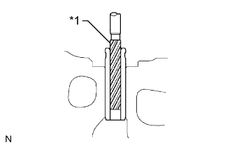
Text in Illustration *1 Sharp 6.0 mm Reamer Using a sharp 6.0 mm reamer, ream the guide bush to obtain the standard clearance between the guide bush and valve stem.
Standard clearance 0.025 to 0.060 mm (0.00984 to 0.00236 in.)
-
-
REPLACE EXHAUST VALVE GUIDE BUSH
-
Gradually heat the cylinder head to approximately 80 to 100°C (176 to 212°F).
-
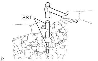
Using SST and a hammer, tap out the valve guide bush.
- SST
- 09201-10000 ( 09201-01060 )
- 09950-70010 ( 09951-07100 )
-
Using a caliper gauge, measure the bush bore diameter of the cylinder head.
-
Select a new guide bush.
New Guide Bush Item Specified Condition Bush bore diameter 10.985 to 11.006 mm (0.4325 to 0.4333 in.) 11.035 to 11.056 mm (0.4344 to 0.4353 in.) Use bush STD O/S 0.05 If the bush bore diameter of the cylinder head is more than 11.006 mm (0.4333 in.), machine the bush bore diameter to between 11.035 and 11.056 mm (0.4344 and 0.4353 in.).
If the bush bore diameter of the cylinder head is more than 11.056 mm (0.4353 in.), replace the cylinder head.
-
Gradually heat the cylinder head to approximately 80 to 100°C (176 to 212°F).
-
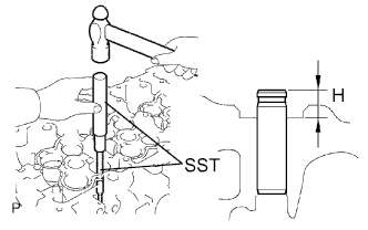
Using SST and a hammer, tap in a new guide bush to the specified protrusion height.
- SST
- 09201-10000 ( 09201-01060 )
- 09950-70010 ( 09951-07100 )
Standard protrusion height (H) 10.3 to 10.7 mm (0.406 to 0.421 in.) -
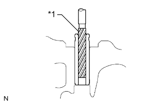
Text in Illustration *1 Sharp 6.0 mm Reamer Using a sharp 6.0 mm reamer, ream the guide bush to obtain the standard clearance between the guide bush and valve stem.
Standard clearance 0.035 to 0.070 mm (0.00138 to 0.00276 in.)
-
-
REPLACE RING PIN
Tech Tips
It is not necessary to remove the ring pin unless it is being replaced.
-
Remove the ring pin.
-
Using a plastic-faced hammer, tap in a new ring pin until the pin stops.
Standard protrusion 3.0 to 4.5 mm (0.118 to 0.177 in.) 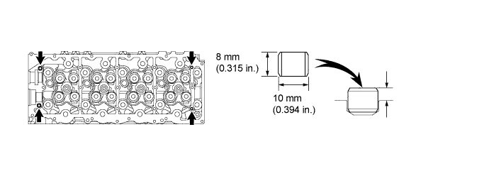
-