ENGINE ASSEMBLY (w/ DPF) REMOVAL

-
DISCONNECT CABLE FROM NEGATIVE BATTERY TERMINAL
Note
-
After turning the ignition switch off, waiting time may be required before disconnecting the cable from the battery terminal. Therefore, make sure to read the disconnecting the cable from the battery terminal notice before proceeding with work Click here.
-
When disconnecting the cable, some systems need to be initialized after the cable is reconnected Click here.
-
-
REMOVE HOOD SUB-ASSEMBLY
-
Disconnect the washer nozzle hose.
-
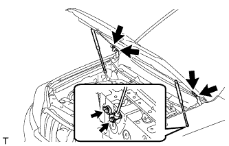
Remove the 8 bolts and hood.
Note
If the hood support is detached from the ball joint, it becomes non-reusable. Therefore, do not detach the hood support from the ball joint unless replacing it.
-
-
REMOVE COWL TOP VENTILATOR LOUVER SUB-ASSEMBLY
-
REMOVE FRONT BUMPER LOWER COVER
-
Remove the clip, 5 bolts and front bumper lower cover.
-
-
REMOVE NO. 1 ENGINE UNDER COVER SUB-ASSEMBLY
-
Remove the 4 bolts and No. 1 engine under cover.
-
-
REMOVE TRANSMISSION UNDER COVER
-
Remove the 2 bolts and transmission under cover.
-
-
REMOVE REAR ENGINE UNDER COVER ASSEMBLY
-
Remove the 4 bolts and rear engine under cover.
-
-
DRAIN ENGINE COOLANT
CAUTION:
Do not remove the radiator cap while the engine and radiator are still hot. Pressurized, hot engine coolant and steam may be released and cause serious burns.
-
Loosen the radiator drain cock plug.
Tech Tips
Collect the coolant in a container and dispose of it according to the regulations in your area.
-
Drain the coolant by removing the reservoir cap and, using a wrench, remove the vent plug.
-
Loosen the cylinder block drain cock plug.
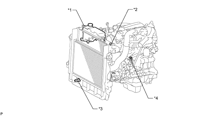
Text in Illustration *1 Radiator Reservoir *2 Vent Plug *3 Radiator Drain Cock Plug *4 Cylinder Block Drain Cock Plug
-
-
DRAIN ENGINE OIL
-
Remove the oil filler cap.
-
Remove the oil pan drain plug and gasket, and then drain the engine oil into a container.
-
Wipe the oil pan and drain plug.
-
Install a new gasket and the oil pan drain plug.
- Torque:
- 34 N*m { 347 kgf*cm, 25 ft.*lbf }
-
-
DRAIN MANUAL TRANSMISSION OIL (for Manual Transmission)
-
Remove the filler plug and gasket.
-
Remove the drain plug and gasket and then drain the manual transmission oil.
-
Install a new gasket and the drain plug.
- Torque:
- 37 N*m { 377 kgf*cm, 27 ft.*lbf }
-
-
DRAIN AUTOMATIC TRANSMISSION FLUID (for Automatic Transmission)
-
Remove the drain plug and gasket, and drain the ATF.
-
Install a new gasket and the drain plug.
- Torque:
- 20 N*m { 204 kgf*cm, 15 ft.*lbf }
-
-
DRAIN POWER STEERING FLUID
-
REMOVE RADIATOR ASSEMBLY
-
REMOVE BATTERY HOLD DOWN CLAMP
-
Remove the 2 nuts and battery hold down clamp.
-
-
REMOVE BATTERY
-
REMOVE BATTERY TRAY
-
REMOVE NO. 1 ENGINE COVER SUB-ASSEMBLY
-
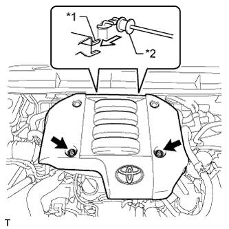
Text in Illustration *1 No. 1 Engine Cover Hook *2 No. 3 Engine Cover Bracket Remove the 2 nuts.
-
Detach the 2 No. 1 engine cover hooks from the No. 3 engine cover bracket and remove the No. 1 engine cover.
-
-
REMOVE NO. 1 AIR CLEANER HOSE
-
Loosen the 2 hose clamps and remove the No. 1 air cleaner hose.
-
-
REMOVE AIR CLEANER CAP SUB-ASSEMBLY
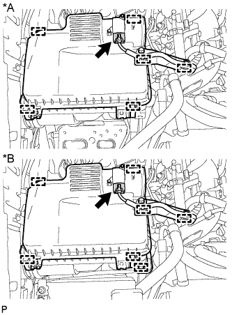
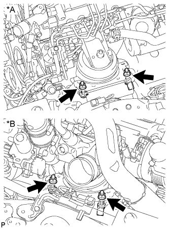
Text in Illustration *A except Cold Area Specification Vehicles *B for Cold Area Specification Vehicles
-
except Cold Area Specification Vehicles:
Detach the 2 clamps and disconnect the mass air flow meter connector.
-
for Cold Area Specification Vehicles:
Detach the 3 clamps and disconnect the mass air flow meter connector.
-
Detach the 4 clamps and remove the air cleaner cap sub-assembly.
-
-
REMOVE AIR CLEANER FILTER ELEMENT SUB-ASSEMBLY
-
REMOVE AIR CLEANER CASE SUB-ASSEMBLY
-
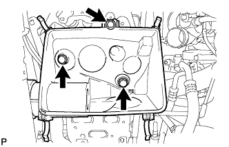
Remove the 3 bolts and air cleaner case sub-assembly.
-
-
REMOVE COMPRESSOR OUTLET ELBOW
-
Detach the 3 wire harness clamps.
-
Remove the bolt and wire harness bracket.
-
Loosen the hose clamp and remove the 2 bolts and compressor outlet elbow.
-
-
REMOVE VISCOUS HEATER WITH MAGNET CLUTCH ASSEMBLY (for Cold Area Specification Vehicles)
-
Disconnect the viscous heater connector.
-
Disconnect the water by-pass hose and water hose.
-
Remove the 2 bolts and viscous heater with magnet clutch.
-
-
REMOVE NO. 1 VISCOUS HEATER BRACKET SUB-ASSEMBLY (for Cold Area Specification Vehicles)
-
Remove the 4 bolts and No. 1 viscous heater bracket.
-
-
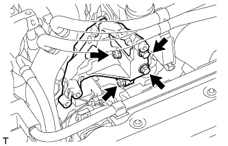
DISCONNECT COOLER COMPRESSOR ASSEMBLY (w/ Air Conditioning System)
-
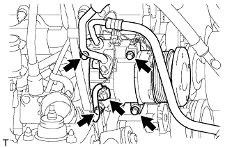
Disconnect the compressor connector.
-
Remove the 4 bolts and disconnect the cooler compressor.
-
-
DISCONNECT NO. 4 VACUUM TRANSMITTING PIPE SUB-ASSEMBLY
-
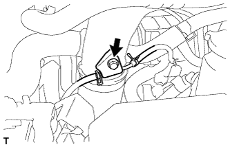
Remove the bolt and disconnect the No. 4 vacuum transmitting pipe.
-
-
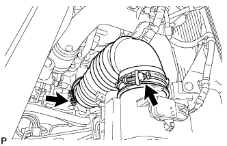
DISCONNECT INTERCOOLER AIR HOSE
-
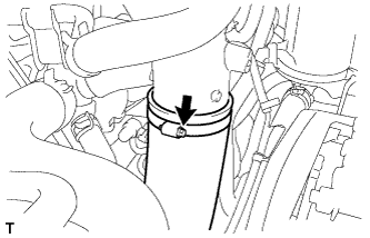
Loosen the hose clamp and disconnect the intercooler air hose.
-
-
REMOVE NO. 1 INTAKE PIPE
-
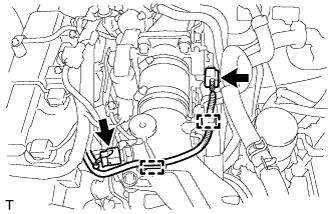
Disconnect the 2 connectors from the intake air temperature sensor and throttle position sensor.
-
Detach the 2 wire harness clamps.
-
Loosen the 2 hose clamps of the No. 1 air hose.
-
Remove the 2 bolts and No. 1 intake pipe.
-
-
REMOVE FUEL FILTER ASSEMBLY
-
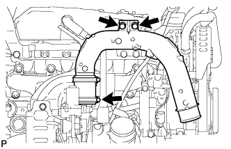
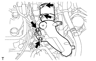
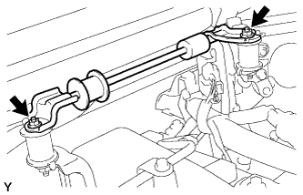
DISCONNECT VANE PUMP OIL RESERVOIR ASSEMBLY
-
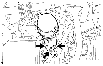
Remove the 3 bolts and disconnect the vane pump oil reservoir.
-
-
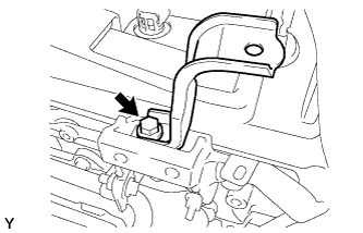
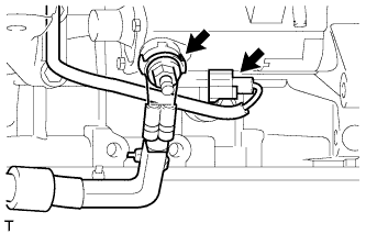
DISCONNECT PRESSURE FEED TUBE ASSEMBLY
-
Disconnect the power steering oil pressure switch connector.
-
Remove the union bolt and gasket and disconnect the pressure feed tube.
-
-
REMOVE NO. 1 ENGINE COVER BRACKET
-
Remove the bolt and No. 1 engine cover bracket.
-
-
REMOVE NO. 3 ENGINE COVER BRACKET
-
Remove the 2 nuts and No. 3 engine cover bracket.
-
-
REMOVE ENGINE COVER BRACKET INSULATOR
-
Remove the 2 nuts and 2 engine cover bracket insulators.
-
-
REMOVE NO. 4 ENGINE COVER BRACKET
-
Remove the bolt and No. 4 engine cover bracket.
-
-
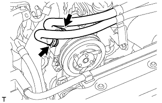
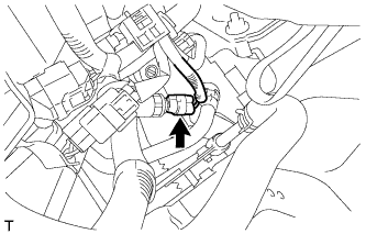
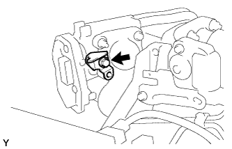
DISCONNECT INLET HEATER WATER HOSE
-
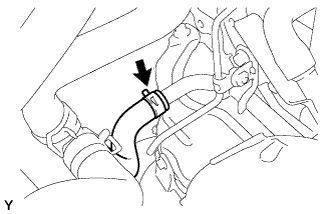
Disconnect the inlet heater water hose.
-
-
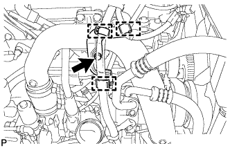
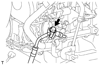
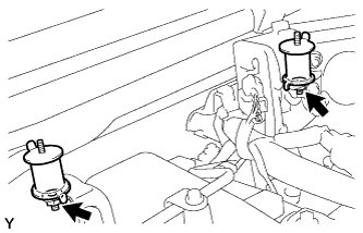
DISCONNECT WATER PIPE AND HOSE SUB-ASSEMBLY
-
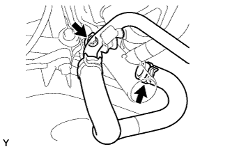
Remove the bolt and disconnect the water pipe and hose.
-
-
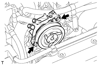
DISCONNECT FUEL HOSE
-
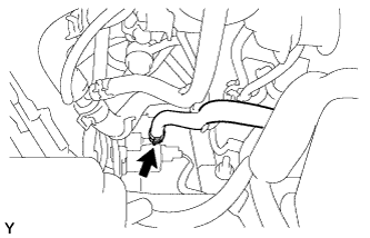
Disconnect the fuel hose from the fuel supply pump.
-
-
DISCONNECT NO. 2 FUEL HOSE
-
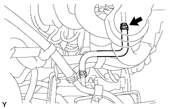
Disconnect the No. 2 fuel hose from the No. 3 nozzle leakage pipe.
-
-
REMOVE GLOVE COMPARTMENT DOOR SUB-ASSEMBLY
-
DISCONNECT ENGINE WIRE
-
Remove the No. 1 relay block cover.
-
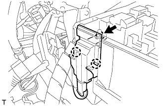
Remove the nut and detach the 2 claws.
-
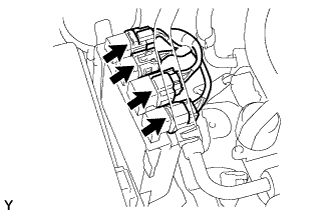
Disconnect the 4 injection driver connectors.
-
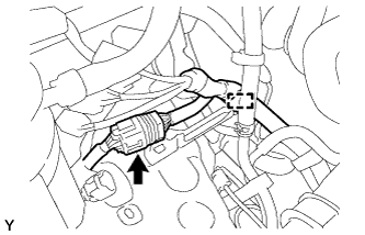
Disconnect the connector and detach the clamp.
-
Remove the bolt.
-
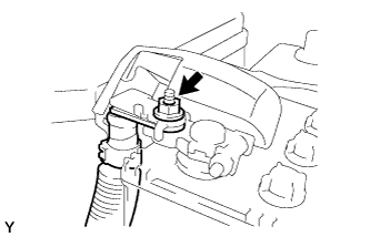
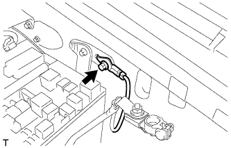
Remove the nut and disconnect the engine wire.
-
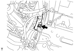
Remove the bolt and disconnect the wire harness protector.
-
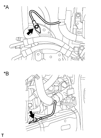
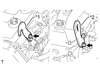
Text in Illustration *A w/ KDSS *B w/o KDSS Remove the bolt and disconnect the engine wire.
-
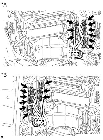
Text in Illustration *A for LHD *B for RHD Detach the clamp and disconnect the 9 connectors.
-
Text in Illustration *A for LHD *B for RHD Detach the grommet from the wire harness support.
-
Text in Illustration *A for LHD *B for RHD Detach the 4 claws and remove the wire harness support from the vehicle, and then pull out the ECM connector to remove it from the vehicle.
-
-
REMOVE STARTER ASSEMBLY (for 2.2 kW Type)
-
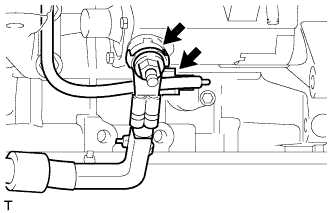
Remove the terminal cap.
-
Remove the nut and disconnect the starter wire.
-
Disconnect the starter connector.
-
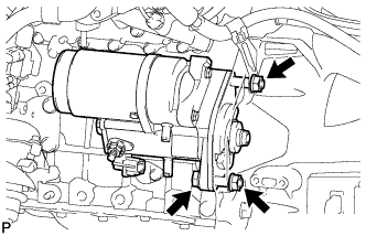
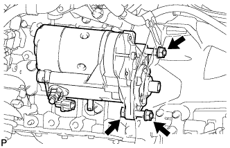
for Automatic Transmission:
Remove the bolt, 2 nuts and starter assembly.
-
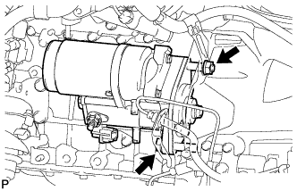
for Manual Transmission:
Remove the bolt, nut and starter assembly.
-
-
REMOVE STARTER ASSEMBLY (for 2.7 kW Type)
-
Remove the terminal cap.
-
Remove the nut and disconnect the starter wire.
-
Disconnect the starter connector.
-
for Automatic Transmission:
Remove the bolt, 2 nuts and starter assembly.
-
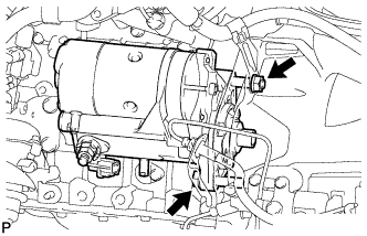
for Manual Transmission:
Remove the bolt, nut and starter assembly.
-
-
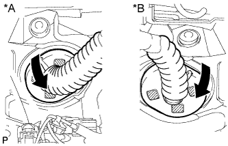
REMOVE FRONT EXHAUST PIPE ASSEMBLY
-
REMOVE FRONT PROPELLER SHAFT ASSEMBLY
-
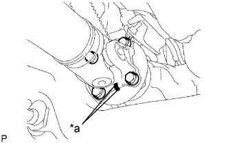
Text in Illustration *a Matchmark Place matchmarks on the propeller shaft flange and differential.
-
Remove the 4 nuts, 4 bolts, 4 washers and front propeller shaft assembly.
-
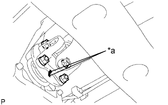
Text in Illustration *a Matchmark Place matchmarks on the propeller shaft flange and transfer flange.
-
Remove the 4 nuts, 4 washers and front propeller shaft assembly.
-
-
REMOVE PROPELLER SHAFT ASSEMBLY
-
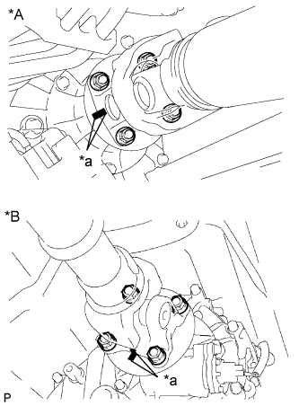
Text in Illustration *A for 3 Door *B for 5 Door *a Matchmark Place matchmarks on the propeller shaft flange and transfer flange.
-
Remove the 4 nuts and 4 washers.
-
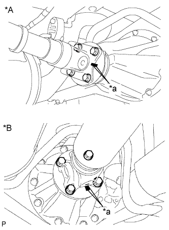
Text in Illustration *A for 3 Door *B for 5 Door *a Matchmark Place matchmarks on the propeller shaft flange and differential flange.
-
Remove the 4 nuts, 4 bolts and 4 washers.
-
Remove the propeller shaft.
-
-
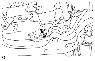
REMOVE OIL PAN INSULATOR
-
Remove the 2 bolts and oil pan insulator.
-
-
REMOVE MANUAL TRANSMISSION ASSEMBLY (for Manual Transmission)
-
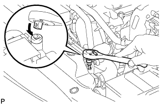
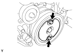
REMOVE DRIVE PLATE AND TORQUE CONVERTER SETTING BOLT (for Automatic Transmission)
-
Turn the crankshaft to gain access to the 6 bolts and remove each bolt while holding the crankshaft pulley bolt with a wrench.
Tech Tips
If it is difficult to reach the setting bolts with the wrench, raise or lower the transmission jack until there is sufficient space for the wrench.
-
-
REMOVE AUTOMATIC TRANSMISSION ASSEMBLY (for Automatic Transmission)
-
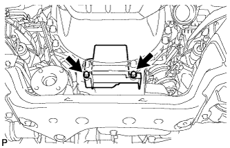
REMOVE REAR NO. 1 ENGINE MOUNTING INSULATOR
Tech Tips
Perform this procedure only when replacement of the rear No. 1 engine mounting insulator is necessary.
-
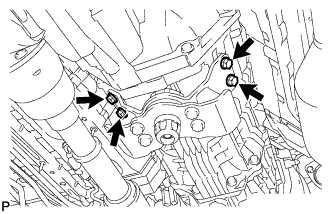
Remove the 4 bolts and rear No. 1 engine mounting insulator.
-
-
REMOVE ENGINE ASSEMBLY
-
Text in Illustration *1 No. 1 Engine Hanger *2 No. 2 Engine Hanger Install 2 engine hangers with 2 bolts as shown in the illustration.
- Torque:
- for No. 1 engine hanger
- 25 N*m { 255 kgf*cm, 18 ft.*lbf }
- for No. 2 engine hanger
- 60 N*m { 612 kgf*cm, 44 ft.*lbf }
Tech Tips
Part No.
No. 1 Engine Hanger 12284-30020 No. 2 Engine Hanger 12282-67030 Bolt 91552-81014 and 91642-81030 Note
Install the engine hangers with new bolts.
-
Attach an engine sling device and hang the engine with a chain block.
-
Text in Illustration *A for LH Side *B for RH Side Remove the 4 bolts and 4 nuts.
-
Remove the engine by operating the engine sling device and chain block.
-
-
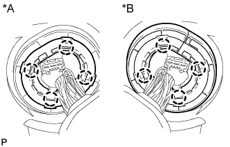
REMOVE CLUTCH COVER ASSEMBLY (for Manual Transmission)
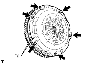
Text in Illustration *a Matchmark
-
Place matchmarks on the clutch cover and flywheel.
-
Loosen each set bolt one turn at a time until spring tension is released.
-
Remove the 6 set bolts and pull off the clutch cover.
Note
Do not drop the clutch disc.
-
-
REMOVE CLUTCH DISC ASSEMBLY (for Manual Transmission)
Note
Keep the lining part of the clutch disc, the pressure plate and the surface of the flywheel away from oil and foreign matter.
-
REMOVE CRANKSHAFT PULLEY COVER
-
Remove the 2 bolts and crankshaft pulley cover.
-
-
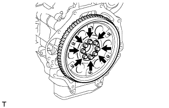
REMOVE FLYWHEEL SUB-ASSEMBLY (for Manual Transmission)
-
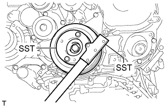
Using SST, hold the crankshaft pulley.
- SST
- 09213-58014
- 09330-00021
-
Remove the 8 bolts and flywheel.
-
-
REMOVE PUMP IMPELLER DRIVE PLATE (for Automatic Transmission)
-
Using SST, hold the crankshaft pulley.
- SST
- 09213-58014
- 09330-00021
-
Remove the 8 bolts, the rear drive plate spacer, the pump impeller drive plate and the flywheel and ring gear.
-
-
REMOVE REAR END PLATE
-
Remove the bolt and rear end plate.
-
-
INSTALL ENGINE TO ENGINE STAND
-
REMOVE ENGINE WIRE
-
Remove the engine wire from the engine.
-
-
REMOVE FRONT ENGINE MOUNTING INSULATOR
-
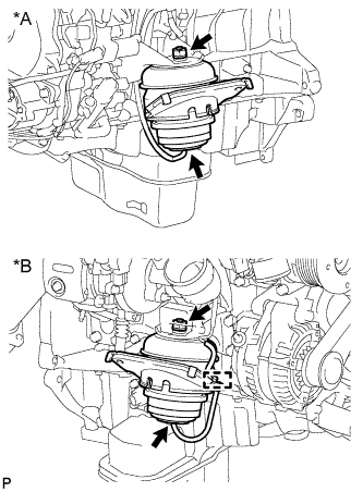
Text in Illustration *A for LH Side *B for RH Side Detach the clamp and disconnect the 2 hoses.
-
Remove the 2 nuts and 2 front engine mounting insulators.
-