CAMSHAFT (w/ DPF) REMOVAL

Note
-
When replacing the injectors (including shuffling the injectors between the cylinders), common rail or cylinder head, it is necessary to replace the injection pipes with new ones.
-
When replacing the fuel supply pump, common rail, cylinder block, cylinder head, cylinder head gasket or timing gear case, it is necessary to replace the fuel inlet pipe with a new one.
-
DISCONNECT CABLE FROM NEGATIVE BATTERY TERMINAL
Note
-
After turning the ignition switch off, waiting time may be required before disconnecting the cable from the battery terminal. Therefore, make sure to read the disconnecting the cable from the battery terminal notice before proceeding with work Click here.
-
When disconnecting the cable, some systems need to be initialized after the cable is reconnected Click here.
-
-
REMOVE FRONT BUMPER LOWER COVER
-
Remove the clip, 5 bolts and front bumper lower cover.
-
-
REMOVE NO. 1 ENGINE UNDER COVER SUB-ASSEMBLY
-
Remove the 4 bolts and No. 1 engine under cover.
-
-
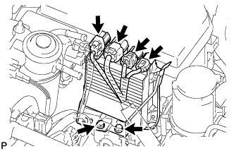
DRAIN ENGINE COOLANT
CAUTION:
Do not remove the radiator reservoir cap while the engine and radiator are still hot. Pressurized, hot engine coolant and steam may be released and cause serious burns.
-
Loosen the radiator drain cock plug.
Tech Tips
Collect the coolant in a container and dispose of it according to the regulations in your area.
-
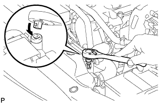
Drain the coolant by removing the reservoir cap and, using a wrench, remove the vent plug.
-
Loosen the cylinder block drain cock plug.
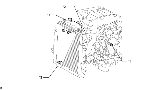
Text in Illustration *1 Radiator Reservoir *2 Vent Plug *3 Radiator Drain Cock Plug *4 Cylinder Block Drain Cock Plug
-
-
REMOVE FRONT WHEEL LH
-
REMOVE FRONT FENDER APRON SEAL LH
-
Remove the 5 clips and front fender apron seal LH.
-
-
REMOVE COWL TOP VENTILATOR LOUVER SUB-ASSEMBLY
-
DISCONNECT NO. 1 ENGINE COVER SUB-ASSEMBLY
-
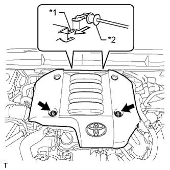
Text in Illustration *1 No. 1 Engine Cover Hook *2 No. 3 Engine Cover Bracket Remove the 2 nuts.
-
Detach the 2 No. 1 engine cover hooks from the No. 3 engine cover bracket and remove the No. 1 engine cover.
-
-
REMOVE UPPER RADIATOR SUPPORT SEAL
-
Remove the 13 clips and upper radiator support seal.
-
-
DISCONNECT NO. 4 VACUUM TRANSMITTING PIPE SUB-ASSEMBLY
-
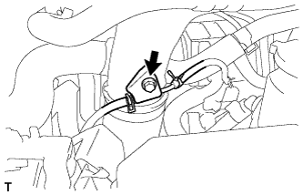
Remove the bolt and disconnect the No. 4 vacuum transmitting pipe.
-
-
DISCONNECT INTERCOOLER AIR HOSE
-
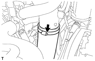
Loosen the hose clamp and disconnect the intercooler air hose.
-
-
REMOVE NO. 1 INTAKE PIPE
-
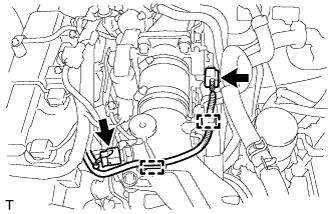
Disconnect the 2 connectors from the intake air temperature sensor and throttle position sensor.
-
Detach the 2 wire harness clamps.
-
Loosen the 2 hose clamps of the No. 1 air hose.
-
Remove the 2 bolts and No. 1 intake pipe.
-
-
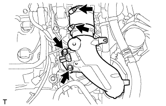
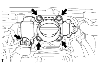
REMOVE DIESEL THROTTLE BODY ASSEMBLY
-
Disconnect the throttle control motor connector.
-
Remove the 2 bolts, 2 nuts, diesel throttle body and gasket.
-
-
REMOVE INJECTOR DRIVER
-
Disconnect the 4 connectors.
-
Remove the 2 bolts and injector driver assembly.
-
-
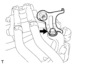
DISCONNECT VANE PUMP OIL RESERVOIR ASSEMBLY
-
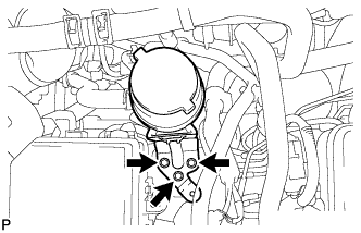
Remove the 3 bolts and disconnect the vane pump oil reservoir.
-
-
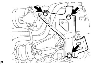
REMOVE MANIFOLD STAY WITH VACUUM SWITCHING VALVE
-
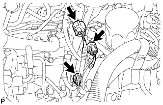
Disconnect the 3 vacuum switching valve connectors.
-
Disconnect the No. 1 vacuum transmitting hose.
-
Disconnect the 2 No. 2 vacuum transmitting hoses from the No. 2 EGR valve.
-
Disconnect the No. 1 vacuum transmitting hose and No. 4 vacuum transmitting hose.
-
Remove the 2 bolts and manifold stay with vacuum switching valve.
-
-
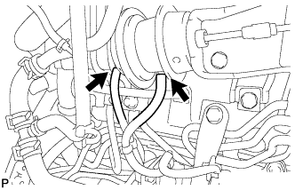
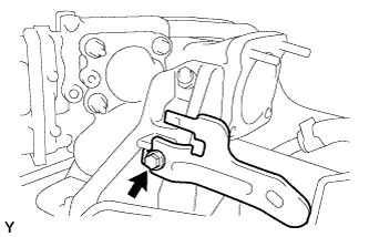
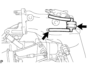
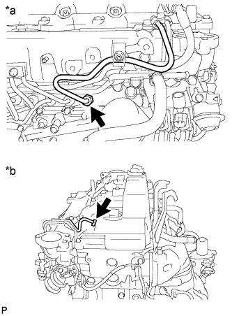
REMOVE FUEL INLET PIPE SUB-ASSEMBLY
-
Remove the bolt and No. 2 injection pipe clamp.
-
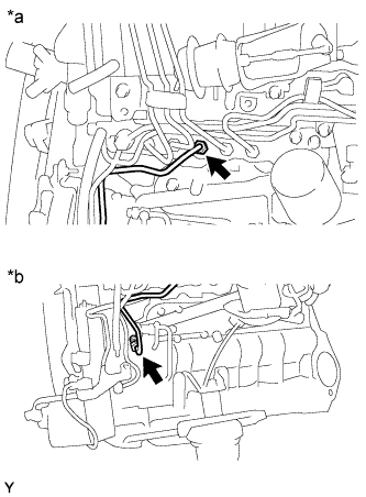
Text in Illustration *a Common Rail Side *b Fuel Supply Pump Side Using a 17 mm union nut wrench, loosen the union nuts and remove the fuel inlet pipe.
-
-
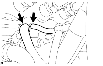
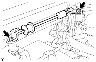
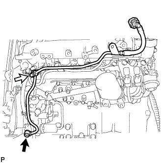
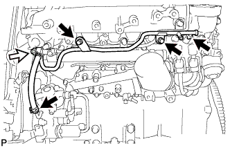
REMOVE NO. 1, NO. 2 AND NO. 3 INJECTION PIPE SUB-ASSEMBLY
Note
-
After removing the injection pipe, cover the outlets on the common rail with tape to keep out foreign matter.
-
After removing the injection pipe, put it in a plastic bag to prevent foreign matter from contaminating its injector inlet.
-
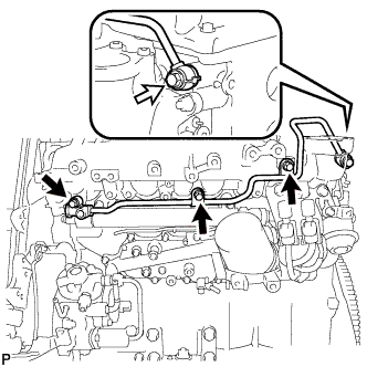
Remove the 2 nuts and No. 3 injection pipe clamp.
-
Remove the 2 bolts and 2 No. 2 injection pipe clamps.
-
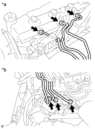
Text in Illustration *a Injector Side *b Common Rail Side Using a 17 mm union nut wrench, loosen the union nuts and remove the No. 1, No. 2 and No. 3 injection pipes.
-
-
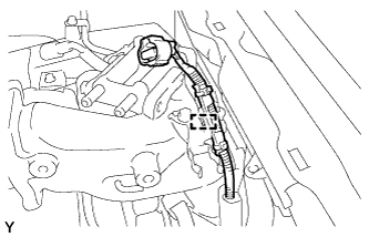
DISCONNECT HEATER WATER PIPE SUB-ASSEMBLY
-
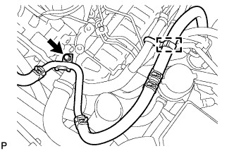
Detach the water by-pass hose clamp.
-
Remove the bolt and disconnect the heater water pipe.
-
-
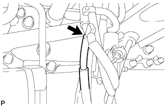
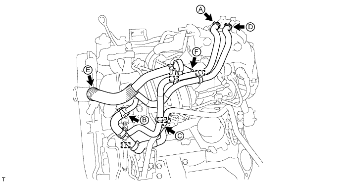
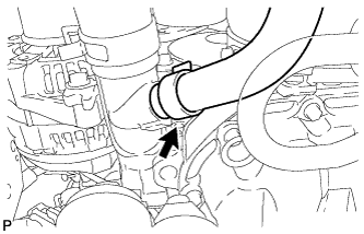
DISCONNECT WATER BY-PASS HOSE
-
Detach the 4 water by-pass hose clamps.
-
Disconnect the No. 7 water by-pass hose labeled A in the illustration.
-
Disconnect the No. 4 water by-pass hose labeled B in the illustration.
-
Disconnect the No. 3 water by-pass hose labeled C in the illustration.
-
Disconnect the No. 8 water by-pass hose labeled D in the illustration.
-
Disconnect the No. 6 water by-pass hose labeled E in the illustration.
-
Disconnect the No. 5 water by-pass hose labeled F in the illustration.
-
-
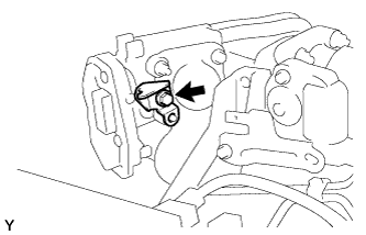
REMOVE NO. 1 VACUUM TRANSMITTING PIPE
-
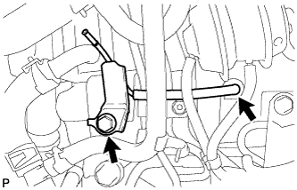
Disconnect the vacuum hose from the intake manifold.
-
Remove the bolt and No. 1 vacuum transmitting pipe.
-
-
REMOVE WIRING HARNESS CLAMP BRACKET
-
Disconnect the glow plug connector.
-
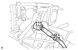
Detach the 2 wire harness clamps and disconnect the glow plug connector from the wiring harness clamp bracket.
-
Remove the bolt and wiring harness clamp bracket.
-
-
REMOVE NO. 3 ENGINE COVER BRACKET
-
Remove the 2 nuts and No. 3 engine cover bracket.
-
-
REMOVE ENGINE COVER BRACKET INSULATOR
-
Remove the 2 nuts and 2 engine cover bracket insulators.
-
-
REMOVE NO. 4 ENGINE COVER BRACKET
-
Remove the bolt and No. 4 engine cover bracket.
-
-
REMOVE AIR CONNECTOR STAY
-
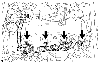
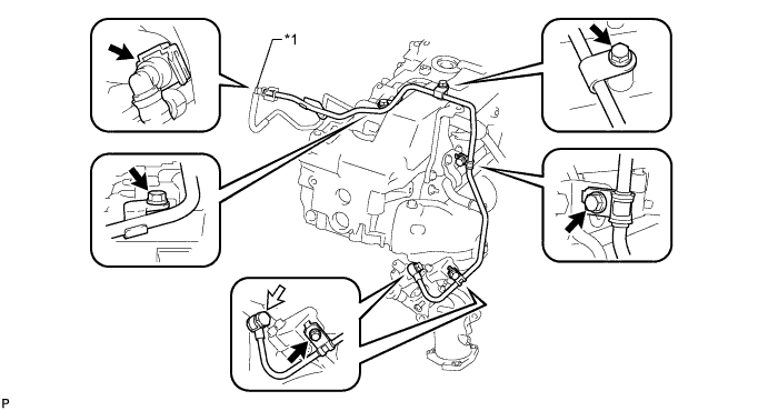
Disconnect the 4 injector connectors and detach the 3 wire harness clamps.
-
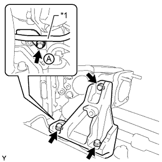
Text in Illustration *1 No. 1 Fuel Pipe Remove the bolt labeled A and disconnect the No. 1 fuel pipe from the air connector stay.
-
Remove the 3 bolts and air connector stay.
-
-
REMOVE EGR COOLER WITH NO. 2 EGR VALVE ASSEMBLY
-
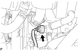
Disconnect the fuel pressure sensor connector from the common rail.
-
Remove the 4 nuts, 3 bolts and EGR cooler with No. 2 EGR valve.
-
Remove the 2 gaskets from the cylinder head and electric EGR control valve.
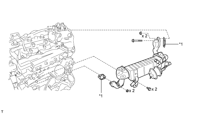
Text in Illustration *1 Gasket - -
-
-
REMOVE ELECTRIC EGR CONTROL VALVE ASSEMBLY
-
Disconnect the electric EGR control valve connector.
-
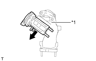
Text in Illustration *1 Intake Air Connector Remove the electric EGR control valve and gasket from the intake air connector.
-
-
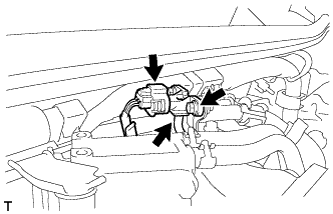
DISCONNECT WIRE HARNESS
-
Remove the bolt and disconnect the wire harness.
-
for LHD:
Remove the bolt and disconnect the wire harness.
-
Detach the 5 clamps and disconnect the wire harness from the cowl top panel.
-
-
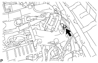
REMOVE MANIFOLD ABSOLUTE PRESSURE SENSOR
-
Disconnect the manifold absolute pressure sensor connector and vacuum hose.
-
Remove the bolt and manifold absolute pressure sensor.
-
-
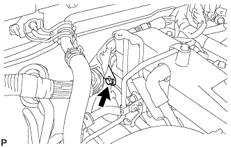
REMOVE EMISSION CONTROL VALVE BRACKET
-
Remove the bolt and emission control valve bracket.
-
-
REMOVE THROTTLE BODY BRACKET
-
Remove the 3 bolts and throttle body bracket.
-
-
REMOVE NO. 1 GAS FILTER
-
Disconnect the vacuum hose and remove the No. 1 gas filter from the gas filter bracket.
-
-
REMOVE GAS FILTER BRACKET
-
Detach the clamp and disconnect the wire harness.
-
Remove the bolt and gas filter bracket.
-
-
REMOVE INTAKE AIR CONNECTOR
-
Remove the 3 bolts, intake air connector and gasket.
-
-
REMOVE NO. 1 FUEL PIPE
-
Disconnect the No. 2 fuel pipe Click here.
-
Remove the 4 bolts, union bolt, gasket and No. 1 fuel pipe.
Text in Illustration *1 No. 2 Fuel Pipe - - 
Union Bolt - -
-
-
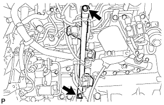
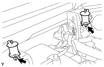
REMOVE NO. 4 INJECTION PIPE SUB-ASSEMBLY
-
Remove the bolt, nut and 2 No. 2 injection pipe clamps.
-
Text in Illustration *a Common Rail Side *b Injector Side Using a 17 mm union nut wrench, loosen the union nuts and remove the No. 4 injection pipe.
-
-
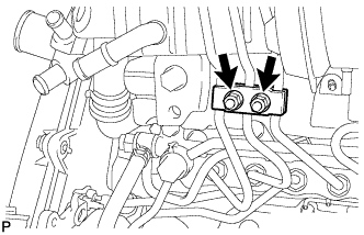
REMOVE NO. 2 FUEL PIPE
-
Using a 6 mm hexagon wrench, remove the union bolt and gasket.
Text in Illustration 
Union Bolt Fuel Check Valve -
Remove the fuel check valve, gasket and No. 2 fuel pipe.
-
-
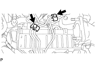
REMOVE NO. 3 NOZZLE LEAKAGE PIPE
-
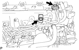
Disconnect the 2 fuel hoses.
Text in Illustration Fuel Check Valve -
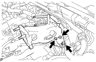
Remove the 2 bolts.
-
Remove the fuel check valve, gasket and No. 3 nozzle leakage pipe.
-
-
REMOVE NO. 2 NOZZLE LEAKAGE PIPE ASSEMBLY
-
Remove the 3 bolts.
Text in Illustration Union Bolt -
Remove the union bolt, gasket and No. 2 nozzle leakage pipe.
-
-
REMOVE NO. 2 CYLINDER HEAD COVER SUB-ASSEMBLY
-
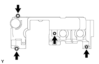
Remove the 4 bolts and No. 2 cylinder head cover.
-
-
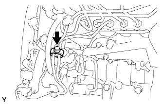
REMOVE VENTILATION PIPE
-
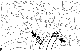
Type A
Slide the 2 clamps and disconnect the No. 3 turbo water hose and No. 4 turbo water hose from the ventilation pipe.
-
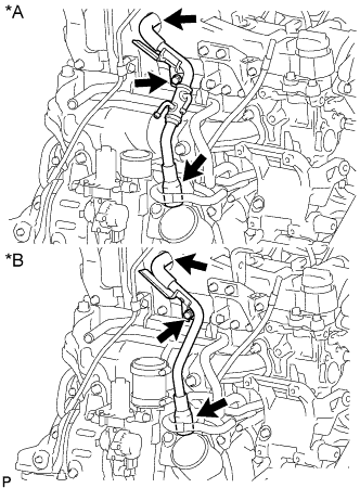
Text in Illustration *A Type A *B Type B Remove the bolt and disconnect the 2 ventilation hoses and ventilation pipe from the cylinder head sub-assembly.
-
-
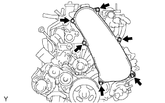
REMOVE CYLINDER HEAD COVER SUB-ASSEMBLY
Note
If the cylinder head cover is removed, replace the 4 No. 3 cylinder head cover gaskets with new ones.
-
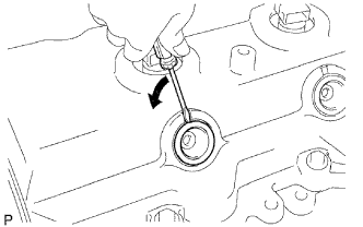
Using a small screwdriver, remove the nozzle holder seal by prying the portion between the nozzle holder seal and the cutout part of the cylinder head cover.
-
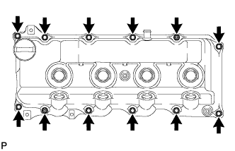
Remove the 10 bolts, 2 nuts, cylinder head cover and cylinder head cover gasket.
-
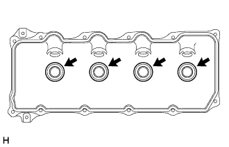
Remove the 4 No. 3 cylinder head cover gaskets from the cylinder head cover.
-
-
REMOVE INJECTOR ASSEMBLY
-
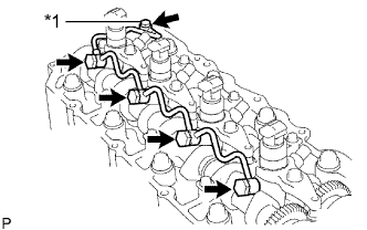
Text in Illustration *1 Union Bolt Remove the union bolt, 4 injector hollow screws, 5 gaskets and nozzle leakage pipe.
Note
-
When removing the nozzle leakage pipe, place a cushion under the pipe.
-
Be careful not to deform or scratch the union seal surface.
-
After removing the nozzle leakage pipe, put it in a plastic bag to prevent foreign matter from contaminating its injector inlet.
-
-
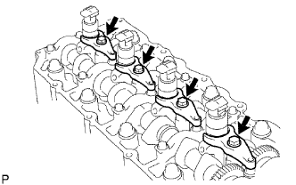
Remove the 4 bolts, 4 washers, 4 No. 1 nozzle holder clamps and 4 injectors.
Tech Tips
Arrange the injectors, No. 1 nozzle holder clamps, washers and bolts in the correct order.
-
Remove the O-ring from each injector.
-
Remove the 4 injection nozzle seats from the cylinder head.
-
-
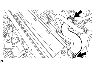
REMOVE NO. 1 RADIATOR HOSE
-
REMOVE FAN SHROUD
-
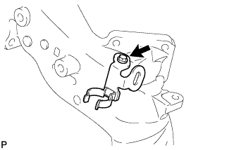
Disconnect the No. 1 water by-pass hose and detach the 2 clamps from the fan shroud.
-
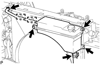
Disconnect the No. 2 water by-pass hose from the radiator reservoir.
-
Remove the 3 bolts and radiator reservoir.
-
for Automatic Transmission:
-
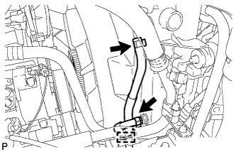
Remove the inlet and outlet oil cooler hoses and detach the clamp from the fan shroud.
-
Disconnect the 2 oil cooler hoses from the radiator.
-
-

Loosen the 4 nuts holding the fan with fluid coupling.
-
Remove the fan and generator V belt Click here.
-
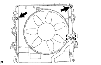
Remove the 2 bolts holding the fan shroud.
-
Remove the 4 nuts for the fan with fluid coupling, and then remove the shroud together with the fan with fluid coupling.
Note
Be careful not to damage the radiator core.
-
Detach the No. 2 water by-pass hose from the hose clamp on the fan shroud.
-
Remove the No. 2 water by-pass hose from the water inlet.
-
Remove the fan pulley from the water pump.
-
-
REMOVE NO. 1 TIMING BELT COVER
-
Remove the 6 bolts, 6 washers and timing belt cover.
-
-
REMOVE TIMING BELT
-
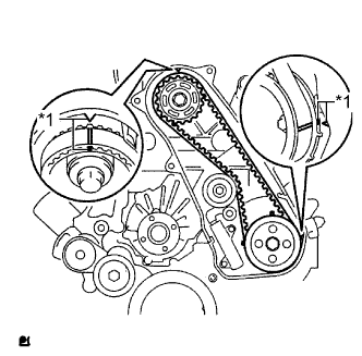
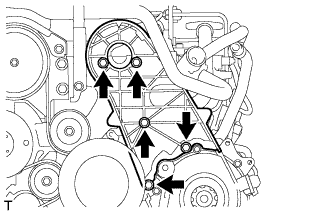
Text in Illustration *1 Timing Mark Turn the crankshaft clockwise and align the timing marks as shown in the illustration.
Tech Tips
If reusing the timing belt, place matchmarks on the timing belt so that it can be installed exactly as before.
-
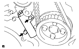
Uniformly loosen and remove the 2 bolts and No. 1 timing belt tensioner.
-
Remove the timing belt.
Tech Tips
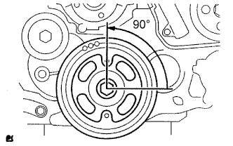
-
If turning the camshaft while the timing belt is removed, turn the crankshaft 90° counterclockwise as shown in the illustration.
-
When installing the timing belt, turn the camshaft to align the timing marks and then turn the crankshaft clockwise to align the timing marks.
-
-
-
REMOVE NO. 1 TIMING BELT IDLER SUB-ASSEMBLY
Note
When inspecting the No. 1 timing belt idler, do not remove it unless absolutely necessary.
-
Using a 10 mm hexagon wrench, remove the bolt, No. 1 timing belt idler and washer.
-
-
REMOVE CAMSHAFT TIMING PULLEY
-
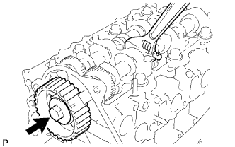
Remove the bolt of the camshaft timing pulley while holding the camshaft with a wrench.
Note
Make sure the timing belt is not installed when removing the bolt of camshaft timing pulley.
-
Remove the camshaft timing pulley.
-
-
REMOVE NO. 2 TIMING BELT COVER
-
Remove the 4 bolts, nut and No. 2 timing belt cover.
-
-
REMOVE CAMSHAFT
-
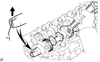
Text in Illustration *1 Key Groove Turn the camshaft with a wrench so that the key groove of the camshaft faces upward.
-
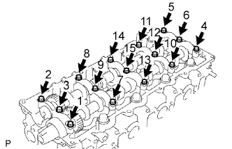
Uniformly loosen the 15 bearing cap bolts in several passes in the sequence shown in the illustration.
-
Remove the 15 bearing cap bolts, 5 bearing caps, oil seal and 2 camshafts.
-