ENGINE UNIT (w/ DPF) INSTALLATION

Note
-
When replacing the injectors (including shuffling the injectors between the cylinders), common rail or cylinder head, it is necessary to replace the injection pipes with new ones.
-
When replacing the fuel supply pump, common rail, cylinder block, cylinder head, cylinder head gasket or timing gear case, it is necessary to replace the fuel inlet pipe with a new one.
-
INSTALL FRONT NO. 1 ENGINE MOUNTING BRACKET
-
Install the 2 engine mounting brackets with the 8 bolts.
- Torque:
- 68 N*m { 694 kgf*cm, 50 ft.*lbf }
-
-
INSTALL NO. 1 OIL PAN COVER SUB-ASSEMBLY
-
Install the No. 1 oil pan cover with the 4 bolts.
- Torque:
- 9.0 N*m { 92 kgf*cm, 80 in.*lbf }
-
-
INSTALL NO. 1 VACUUM TRANSMITTING PIPE SUB-ASSEMBLY
-
Install the No. 1 vacuum transmitting pipe with the bolt and nut.
- Torque:
- for bolt
- 13 N*m { 133 kgf*cm, 10 ft.*lbf }
- for nut
- 8.0 N*m { 82 kgf*cm, 71 in.*lbf }
-
-
INSTALL OIL COOLER COVER SUB-ASSEMBLY
-
Install the oil cooler cover with the 13 bolts.
- Torque:
- 13 N*m { 133 kgf*cm, 10 ft.*lbf }
-
-
INSTALL NO. 2 VACUUM TRANSMITTING PIPE SUB-ASSEMBLY
-
Install the No. 2 vacuum transmitting pipe with the 2 nuts.
- Torque:
- 13 N*m { 133 kgf*cm, 10 ft.*lbf }
-
Connect the vacuum hose.
-
-
INSTALL WATER OUTLET
-
Install a new gasket and the water outlet with the 2 bolts.
- Torque:
- 19 N*m { 194 kgf*cm, 14 ft.*lbf }
-
-
INSTALL PUMP DRIVE SHAFT PULLEY
-
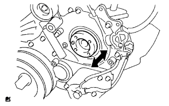
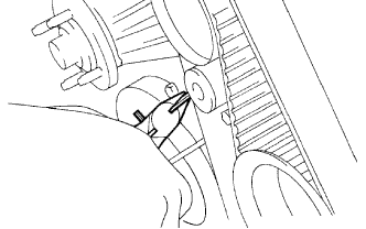
Check that the injection gear in the timing gear case moves back and forth smoothly.
-
Install the pump drive shaft pulley and No. 2 camshaft timing pulley flange with the 4 bolts.
- Torque:
- 31 N*m { 316 kgf*cm, 23 ft.*lbf }
-
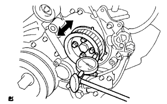
Move the pump drive shaft pulley back and forth to check the thrust clearance of the injection pump drive shaft.
Standard thrust clearance 0.15 to 0.55 mm (0.00590 to 0.0217 in.) If the clearance is not within the specified range, disassemble and reassemble the fuel supply pump and pump drive shaft pulley. Then repeat the step above.
-
-
INSTALL NO. 1 INJECTION PUMP PROTECTOR
-
Install the No. 1 injection pump protector with the 2 bolts.
- Torque:
- 29 N*m { 296 kgf*cm, 21 ft.*lbf }
-
-
INSTALL INJECTION PUMP INSULATOR
-
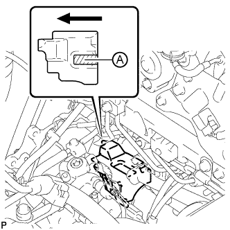
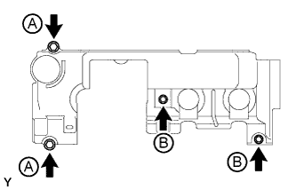
Install the injection pump insulator.
Text in Illustration 
Front Side of Vehicle Note
-
When installing the injection pump insulator, be sure to hold down the part labeled A in the illustration.
-
Make sure that the shape of the injection pump insulator fits correctly with the timing gear case assembly, cylinder block sub-assembly and oil cooler cover.
-
-
-
INSTALL NO. 2 INTAKE MANIFOLD INSULATOR
-
Install the No. 2 intake manifold insulator.
-
-
INSTALL COMMON RAIL ASSEMBLY
-
Install the common rail assembly with the 2 bolts.
- Torque:
- 38 N*m { 387 kgf*cm, 28 ft.*lbf }
-
Connect the pressure discharge valve connector.
-
-
INSTALL OIL FILTER SUB-ASSEMBLY
-
Check and clean the oil filter installation surface.
-
Apply clean engine oil to the gasket of a new oil filter.
-
Lightly screw the oil filter into place by hand. Tighten it until the gasket contacts the seat.
-
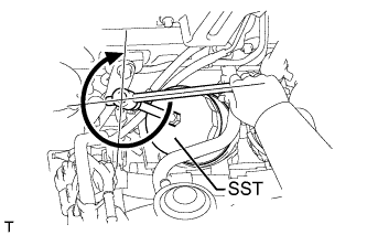
Using SST, tighten the oil filter. Depending on the space available, choose from the following.
- SST
- 09228-07501
-
If enough space is available, use a torque wrench to tighten the oil filter.
- Torque:
- 17 N*m { 173 kgf*cm, 13 ft.*lbf }
-
If enough space is not available to use a torque wrench, tighten the oil filter 3/4 of a turn by hand or with a common wrench.
-
-
INSTALL GLOW PLUG ASSEMBLY
Note
-
Measure the resistance of the glow plug when reinstalling it. If the result is not as specified, replace the glow plug with a new one.
-
Replace the glow plug with a new one when it has been dropped or subjected to a physical impact.
-
Remove any carbon deposits from the glow plug hole when reinstalling the glow plug.
-
Clean the glow plug hole.
-
Wrap tape around a drill bit with a diameter of 4.4 mm (0.173 in.), 118.5 mm (4.665 in.) from its tip.
-
Insert the drill bit 118.5 mm (4.665 in.) into the glow plug hole (up to the tape) and remove any carbon deposits by turning the drill bit by hand.
-
Insert a drill bit with a diameter of 4 mm (0.157 in.) into the glow plug hole and remove any carbon deposits from the end of the glow plug hole by turning the drill bit by hand.
-
-
Using a 12 mm deep socket wrench, install the glow plug assembly.
- Torque:
- 18 N*m { 178 kgf*cm, 13 ft.*lbf }
Note
Do not use any tools, such as air tools, which are liable to cause an impact to the glow plugs when installing them.
-
-
INSTALL NO. 1 INTAKE MANIFOLD INSULATOR
-
Install the No. 1 intake manifold insulator.
-
-
INSTALL NO. 1 GLOW PLUG CONNECTOR
-
Temporarily install the No. 1 glow plug connector with the 4 nuts.
-
Tighten the 4 nuts.
- Torque:
- 2.2 N*m { 22 kgf*cm, 19 in.*lbf }
-
Install the 4 screw grommets.
-
Connect the No. 1 glow plug connector to the wire harness.
-
-
INSTALL INTAKE MANIFOLD
-
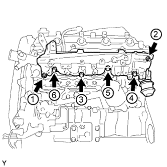
Temporarily install a new gasket and the intake manifold with the 2 nuts and 4 bolts.
-
Tighten the 2 nuts and 4 bolts in the order shown in the illustration.
- Torque:
- 29 N*m { 296 kgf*cm, 21 ft.*lbf }
Note
Make sure that the swirl control valve actuator is not damaged by the surrounding parts.
-
Attach the sensor wire connector clamp to the intake manifold.
-
-
INSTALL INTAKE MANIFOLD INSULATOR
-
Install the intake manifold insulator.
-
-
INSTALL INTAKE PIPE STAY
-
Install the intake pipe stay with the bolt.
- Torque:
- 23 N*m { 235 kgf*cm, 17 ft.*lbf }
-
-
INSTALL VACUUM CONTROL VALVE SET
-
Install the vacuum control valve set with the 2 bolts.
- Torque:
- 20 N*m { 204 kgf*cm, 15 ft.*lbf }
-
Text in Illustration *1 White Paint Mark *2 Green Paint Mark *3 Swirl Control Valve Actuator Connect the 3 vacuum hoses and 2 vacuum switching valve connectors.
Note
When connecting the hoses, match the colors of the paint marks on the hoses to the colors of the paint marks on the swirl control valve as shown in the illustration.
-
-
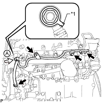
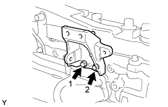
INSTALL NO. 2 NOZZLE LEAKAGE PIPE ASSEMBLY
-
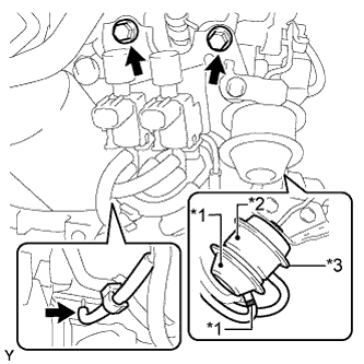
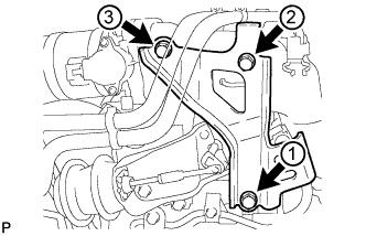
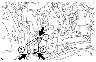
Temporarily install the No. 2 nozzle leakage pipe assembly with the 2 bolts.
Text in Illustration 
Union Bolt -
Temporarily install a new gasket and the union bolt.
-
Tighten the 2 bolts and union bolt.
- Torque:
- for bolt A
- 21 N*m { 214 kgf*cm, 15 ft.*lbf }
- for bolt B
- 13 N*m { 130 kgf*cm, 9 ft.*lbf }
- for union bolt
- 21 N*m { 214 kgf*cm, 15 ft.*lbf }
-
-
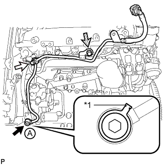
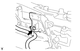
INSTALL NO. 3 NOZZLE LEAKAGE PIPE
-
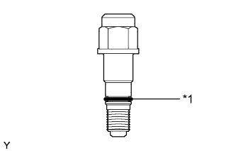
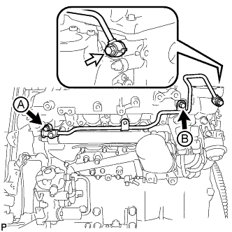
Text in Illustration *1 O-Ring Apply a light coat of fuel to the O-ring of the fuel check valve.
-
Text in Illustration *1 Gasket Fuel Check Valve Temporarily install the No. 3 nozzle leakage pipe with the 2 bolts.
-
Temporarily install a new gasket and fuel check valve.
-
Tighten the 2 bolts and fuel check valve.
- Torque:
- for bolt
- 13 N*m { 130 kgf*cm, 9 ft.*lbf }
- for fuel check valve
- 32 N*m { 321 kgf*cm, 23 ft.*lbf }
Note
Make sure the gasket of fuel check valve A contacts the No. 3 nozzle leakage pipe as shown in the illustration when tightening the fuel check valve.
-
Connect the 2 fuel hoses.
-
-
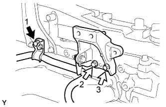
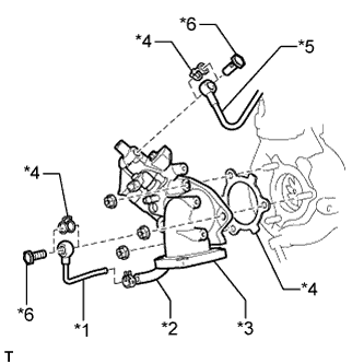
INSTALL NO. 2 FUEL PIPE
-
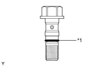
Text in Illustration *1 O-Ring Apply a light coat of fuel to the O-ring of the fuel check valve.
-
Text in Illustration *1 Gasket Union Bolt Fuel Check Valve 
Bolt Temporarily install the No. 2 fuel pipe with a new gasket and the union bolt.
-
Temporarily install a new gasket and the fuel check valve.
-
Temporarily install the bolt.
-
Using a 6 mm hexagon wrench, tighten the union bolt.
- Torque:
- 21 N*m { 214 kgf*cm, 15 ft.*lbf }
Note
Make sure the gasket of union bolt A contacts the No. 2 fuel pipe as shown in the illustration when tightening the union bolt.
-
Tighten the fuel check valve.
- Torque:
- 32 N*m { 321 kgf*cm, 23 ft.*lbf }
-
Tighten the bolt.
- Torque:
- 13 N*m { 130 kgf*cm, 9 ft.*lbf }
-
-
INSTALL NO. 4 INJECTION PIPE SUB-ASSEMBLY
Note
-
When replacing an injector assembly, it is necessary to replace the 4 injection pipe sub-assemblies with new ones.
-
Keep the joints of the injection pipe sub-assembly clean.
-
Temporarily install the No. 4 injection pipe with the union nuts.
-
Install the 2 No. 2 injection pipe clamps with the bolt and nut.
- Torque:
- 6.5 N*m { 66 kgf*cm, 58 in.*lbf }
-
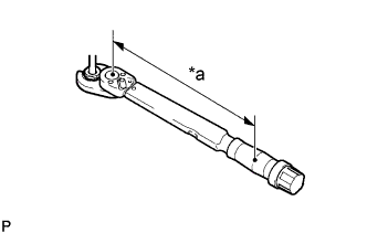
Text in Illustration *a Torque Wrench Fulcrum Length Using a 17 mm union nut wrench, tighten the No. 4 injection pipe sub-assembly union nut on the common rail assembly side.
- Torque:
- Specified tightening torque
- 35 N*m { 357 kgf*cm, 26 ft.*lbf }
Tech Tips
-
Calculate the torque wrench reading when changing the fulcrum length of the torque wrench Click here.
-
When using a union nut wrench (fulcrum length of 30 mm (1.1811 in.)) + torque wrench (fulcrum length of 300 mm (11.8110 in.)): 32 N*m (324 kgf*cm, 23 ft.*lbf)
-
Text in Illustration *a Torque Wrench Fulcrum Length Using a 17 mm union nut wrench, tighten the injection pipe sub-assembly union nuts on the injector assembly side.
- Torque:
- Specified tightening torque
- 35 N*m { 357 kgf*cm, 26 ft.*lbf }
Tech Tips
-
Calculate the torque wrench reading when changing the fulcrum length of the torque wrench Click here.
-
When using a union nut wrench (fulcrum length of 30 mm (1.1811 in.)) + torque wrench (fulcrum length of 300 mm (11.8110 in.)): 32 N*m (324 kgf*cm, 23 ft.*lbf)
-
-
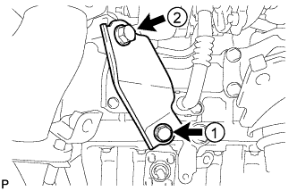
INSTALL EGR COOLER INSULATOR
-
Install the 2 EGR cooler insulators to the EGR cooler.
Tech Tips
Install the EGR cooler insulators so that they are positioned as shown in the illustration.
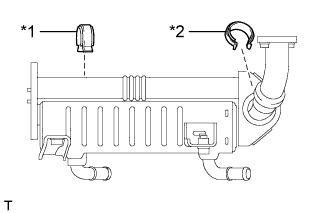
Text in Illustration *1 No. 2 EGR Cooler Insulator *2 No. 1 EGR Cooler Insulator
-
-
INSTALL NO. 2 EGR VALVE ASSEMBLY
-
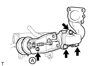
Using a 6 mm hexagon wrench, install 2 new gaskets, the EGR valve adapter, No. 2 EGR valve, EGR cooler and 3 plate washers with the 3 hexagon bolts.
- Torque:
- 28 N*m { 286 kgf*cm, 21 ft.*lbf }
-
Install the bolt labeled A.
- Torque:
- 13 N*m { 133 kgf*cm, 10 ft.*lbf }
-
-
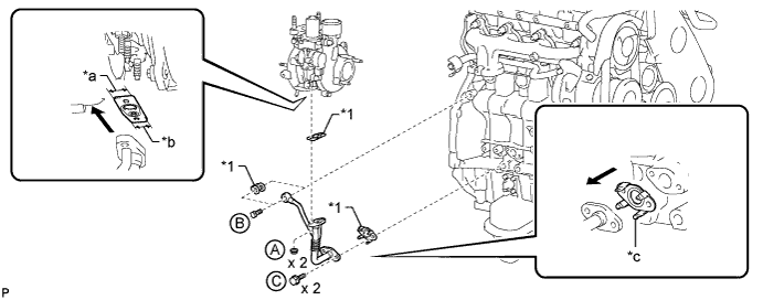
TEMPORARILY INSTALL ELECTRIC EGR CONTROL VALVE ASSEMBLY
-
Set the electric EGR control valve between 2 new gaskets onto the stud bolt of the intake air connector.
-
Temporarily install the intake air connector and electric EGR control valve to the EGR valve adapter with the 2 nuts and bolt.
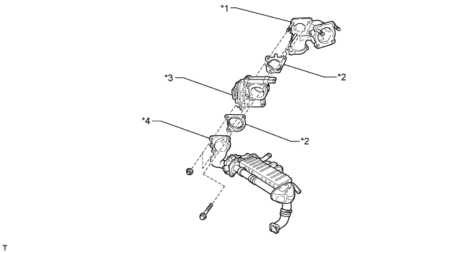
Text in Illustration *1 Intake Air Connector *2 New Gasket *3 Electric EGR Control Valve *4 EGR Valve Adapter -
Set a new gasket on the intake manifold.
Tech Tips
Make sure the claws of the gasket face the intake manifold.
-
Set a new gasket onto the stud bolts of the cylinder head.
-
Temporarily install the intake air connector to the intake manifold with the 3 bolts labeled A in the illustration.
-
Temporarily install the EGR cooler to the intake manifold with the 2 bolts labeled B in the illustration.
-
Temporarily install the EGR cooler to the cylinder head with the 2 nuts labeled C in the illustration.
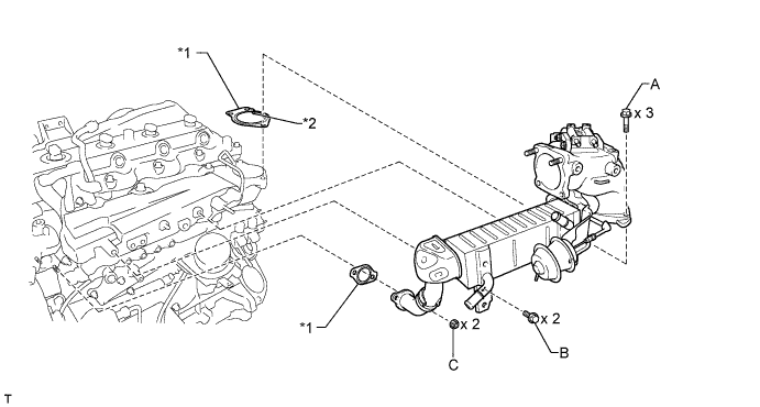
Text in Illustration *1 New Gasket *2 Claw
-
-
TIGHTEN ELECTRIC EGR CONTROL VALVE ASSEMBLY
-
Tighten the 3 bolts labeled A in the illustration.
- Torque:
- 20 N*m { 204 kgf*cm, 15 ft.*lbf }
-
Tighten the 2 bolts labeled B in the illustration.
- Torque:
- 20 N*m { 204 kgf*cm, 15 ft.*lbf }
-
Tighten the 2 nuts labeled C in the illustration.
- Torque:
- 13 N*m { 133 kgf*cm, 10 ft.*lbf }
-
Install the air connector stay with the 3 bolts labeled D in the illustration.
- Torque:
- 20 N*m { 204 kgf*cm, 15 ft.*lbf }
-
Tighten the 2 nuts and bolt labeled E in the illustration.
- Torque:
- 20 N*m { 204 kgf*cm, 15 ft.*lbf }
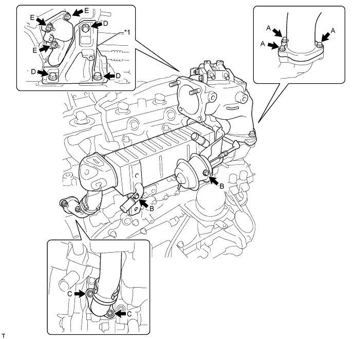
Text in Illustration *1 Air Connector Stay - -
-
-
INSTALL NO. 1, NO. 2 AND NO. 3 INJECTION PIPE SUB-ASSEMBLY
Note
-
When replacing an injector, it is necessary to replace the 4 injection pipes with new ones.
-
Keep the joints of the injection pipe clean.
-
Temporarily install the No. 1, No. 2 and No. 3 injection pipes with the union nuts.
-
Install the 2 No. 2 injection pipe clamps with the 2 bolts.
- Torque:
- 6.5 N*m { 66 kgf*cm, 58 in.*lbf }
-
Install the No. 3 injection pipe clamp with the 2 nuts.
- Torque:
- 6.5 N*m { 66 kgf*cm, 58 in.*lbf }
-
Using a 17 mm union nut wrench, tighten the injection pipe union nuts on the common rail side.
- Torque:
- 35 N*m { 357 kgf*cm, 26 ft.*lbf }
Note
Use the formula to calculate special torque values for situations where a union nut wrench is combined with a torque wrench Click here.
-
Using a 17 mm union nut wrench, tighten the injection pipe union nuts on the injector side.
- Torque:
- 35 N*m { 357 kgf*cm, 26 ft.*lbf }
Note
Use the formula to calculate special torque values for situations where a union nut wrench is combined with a torque wrench Click here.
-
-
INSTALL WIRING HARNESS CLAMP BRACKET
-
Install the wiring harness clamp bracket.
- Torque:
- 8.0 N*m { 82 kgf*cm, 71 in.*lbf }
-
Attach the 2 wire harness clamps and connect the glow plug connector to the wiring harness clamp bracket.
-
Connect the glow plug connector.
-
-
INSTALL FUEL INLET PIPE SUB-ASSEMBLY
Note
-
When replacing an injector, it is necessary to replace the 4 injection pipes with new ones.
-
Keep the joints of the injection pipe clean.
-
Temporarily install the No. 1, No. 2 and No. 3 injection pipes with the union nuts.
-
Install the 2 No. 2 injection pipe clamps with the 2 bolts.
- Torque:
- 6.5 N*m { 66 kgf*cm, 58 in.*lbf }
-
Install the No. 3 injection pipe clamp with the 2 nuts.
- Torque:
- 6.5 N*m { 66 kgf*cm, 58 in.*lbf }
-
Using a 17 mm union nut wrench, tighten the injection pipe union nuts on the common rail side.
- Torque:
- 35 N*m { 357 kgf*cm, 26 ft.*lbf }
Note
Use the formula to calculate special torque values for situations where a union nut wrench is combined with a torque wrench Click here.
-
Using a 17 mm union nut wrench, tighten the injection pipe union nuts on the injector side.
- Torque:
- 35 N*m { 357 kgf*cm, 26 ft.*lbf }
Note
Use the formula to calculate special torque values for situations where a union nut wrench is combined with a torque wrench Click here.
-
-
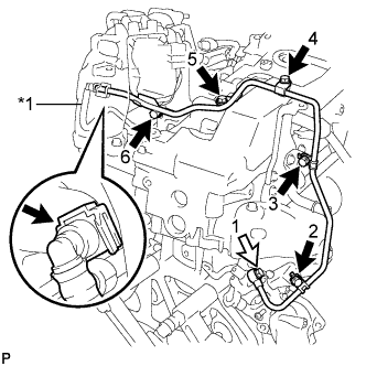
INSTALL WATER BY-PASS HOSE
Tech Tips
-
When connecting the hoses, make sure the paint marks and clips are as shown in the illustration.
-
The direction of each hose clamp is indicated in the illustration.
-
Connect the No. 5 water by-pass hose labeled A in the illustration.
-
Connect the No. 6 water by-pass hose labeled B in the illustration.
-
Connect the No. 8 water by-pass hose labeled C in the illustration.
-
Connect the No. 3 water by-pass hose labeled D in the illustration.
-
Connect the No. 4 water by-pass hose labeled E in the illustration.
-
Connect the No. 7 water by-pass hose labeled F in the illustration.
-
Attach the 4 water by-pass hose clamps.
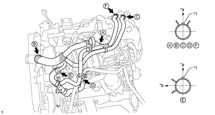
Text in Illustration *1 Paint Mark - - *a Upper Side *b LH Side
-
-
INSTALL MANIFOLD STAY WITH VACUUM SWITCHING VALVE
-
Text in Illustration *1 White Mark *2 Blue Mark Install the manifold stay with vacuum switching valve with the 2 bolts and connect the No. 4 vacuum transmitting hose and No. 1 vacuum transmitting hose.
- Torque:
- 19 N*m { 194 kgf*cm, 14 ft.*lbf }
Note
Make sure the vacuum transmitting hose color matches the connection area color.
-
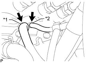
Text in Illustration *1 Yellow Mark *2 No. 2 EGR Valve Connect the 2 No. 2 vacuum transmitting hoses shown in the illustration.
Tech Tips
-
Make sure that the vacuum transmitting hose with the yellow mark is connected to the side of the No. 2 EGR valve that has a yellow mark as shown in the illustration.
-
Push on the vacuum transmitting hose until it reaches the bent part of the pipe.
-
-
Connect the No. 1 vacuum transmitting hose.
-
Connect the 3 vacuum switching valve connectors.
-
-
INSTALL NO. 1 VACUUM TRANSMITTING PIPE
-
Install the No. 1 vacuum transmitting pipe with the bolt.
- Torque:
- 18 N*m { 178 kgf*cm, 13 ft.*lbf }
-
Connect the vacuum hose to the intake manifold.
-
-
INSTALL NO. 2 CYLINDER HEAD COVER SUB-ASSEMBLY
-
Install the No. 2 cylinder head cover sub-assembly with the 4 bolts.
- Torque:
- for bolt A
- 18 N*m { 184 kgf*cm, 13 ft.*lbf }
- for bolt B
- 8.0 N*m { 82 kgf*cm, 71 in.*lbf }
-
-
INSTALL GAS FILTER BRACKET
-
Install the gas filter bracket with the bolt.
- Torque:
- 8.0 N*m { 82 kgf*cm, 71 in.*lbf }
-
Attach the clamp and connect the wire harness.
-
-
INSTALL NO. 1 GAS FILTER
-
Install the No. 1gas filter to the gas filter bracket.
-
Connect the vacuum hose.
-
-
INSTALL THROTTLE BODY BRACKET
-
Temporarily install the throttle body bracket with the 3 bolts.
-
Tighten the 3 bolts of the throttle body bracket in the order shown in the illustration.
- Torque:
- 20 N*m { 204 kgf*cm, 15 ft.*lbf }
-
-
INSTALL EMISSION CONTROL VALVE BRACKET
-
Install the emission control valve bracket with the bolt.
- Torque:
- 13 N*m { 133 kgf*cm, 10 ft.*lbf }
-
-
INSTALL MANIFOLD ABSOLUTE PRESSURE SENSOR
-
Install the manifold absolute pressure sensor with the bolt.
- Torque:
- 8.0 N*m { 82 kgf*cm, 71 in.*lbf }
-
Connect the vacuum hose and manifold absolute pressure sensor connector.
-
-
INSTALL DIESEL THROTTLE BODY ASSEMBLY
-
Install a new gasket and the diesel throttle body with the 2 bolts and 2 nuts.
- Torque:
- 20 N*m { 204 kgf*cm, 15 ft.*lbf }
-
Connect the throttle control motor connector.
-
-
INSTALL CRANKSHAFT PULLEY
-
Align the keyway of the pulley with the key located on the crankshaft, and then slide the pulley into place to install it.
-
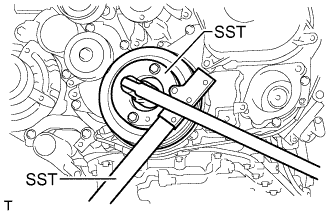
Using SST, install the pulley bolt.
- SST
- 09213-58014
- 09330-00021
- Torque:
- 365 N*m { 3722 kgf*cm, 269 ft.*lbf }
-
-
INSTALL NO. 1 TIMING BELT IDLER SUB-ASSEMBLY
-
Using a 10 mm hexagon wrench, install a new washer and the No. 1 timing belt idler with the bolt.
- Torque:
- 35 N*m { 357 kgf*cm, 26 ft.*lbf }
-
Check that the idler pulley moves smoothly.
If the idler pulley does not move smoothly, check the installation condition of the idler and washer.
-
-
INSTALL TIMING BELT
-
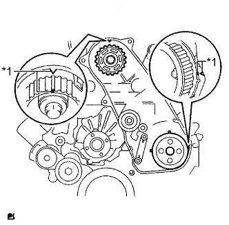
Text in Illustration *1 Timing Mark Check that the timing marks are aligned as shown in the illustration.
Tech Tips
If reusing the timing belt, align the points marked during removal, and install the belt with the arrow pointing in the direction of crankshaft revolution.
Note
-
Make sure that the engine is cold.
-
When turning the crankshaft, the valve heads will hit against the piston. Do not turn the crankshaft more than necessary.
-
-
Install the timing belt to the pump drive shaft pulley, camshaft timing pulley and No. 1 timing belt idler in sequence.
-
Place the tensioner upright. Then set a press on the top of the tensioner.
Note
-
Do not scratch or deform the rod end.
-
Press in the tensioner rod.
-
Protect the tip of the push rod with a cloth in order to prevent damage.
-
-
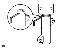
Using the press, slowly push in the push rod using 981 to 9807 N (100 to 1000 kgf, 220 to 2205 lbf) of force.
Note
Do not apply a load of over 9807 N (1000 kgf, 2205 lbf) to the push rod.
-
Align the holes of the push rod and housing. Then pass a 1.5 mm hexagon wrench through the holes to fix the push rod in place.
-
Temporarily install the timing belt tensioner with the 2 bolts while pushing the idler pulley toward the timing belt.
-
Tighten the 2 bolts.
- Torque:
- 13 N*m { 133 kgf*cm, 10 ft.*lbf }
Note
Uniformly tighten the 2 bolts.
-
Remove the 1.5 mm hexagon wrench from the tensioner.
-
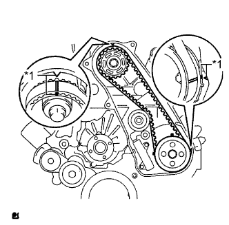
Text in Illustration *1 Timing Mark Turn the crankshaft clockwise 720° and check that the timing marks are aligned as shown in the illustration.
-
-
INSTALL NO. 1 TIMING BELT COVER
-
Install the timing belt cover and 6 washers with the 6 bolts.
- Torque:
- 6.0 N*m { 61 kgf*cm, 53 in.*lbf }
-
-
INSTALL VANE PUMP ASSEMBLY
-
Install a new O-ring and the vane pump with the 2 nuts.
- Torque:
- 41 N*m { 418 kgf*cm, 30 ft.*lbf }
-
-
INSTALL VACUUM PUMP ASSEMBLY
-
Install 2 new O-rings to the vacuum pump.
-
Install the vacuum pump with the 2 nuts.
- Torque:
- 21 N*m { 210 kgf*cm, 15 ft.*lbf }
-
Install the bracket with the bolt.
- Torque:
- 13 N*m { 133 kgf*cm, 10 ft.*lbf }
-
-
INSTALL CRANKSHAFT POSITION SENSOR
-
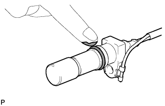
Apply a light coat of engine oil to the O-ring of the crankshaft position sensor.
-
Install the crankshaft position sensor with the bolt.
- Torque:
- 8.5 N*m { 87 kgf*cm, 75 in.*lbf }
Note
Make sure that the O-ring is not damaged or does not jump out of position during installation.
-
Install the bracket (clamp) with the bolt.
- Torque:
- 13 N*m { 133 kgf*cm, 10 ft.*lbf }
-
Install a new clamp.
Note
-
Make sure that no portion of the clamp remains in the clamp installation hole. If there is any portion of the clamp remaining, remove it.
-
Make sure the crankshaft position sensor wire harness is installed in the position shown in the illustration.
-
-
Attach the crankshaft position sensor connector to the No. 1 vacuum transmitting pipe.
-
Connect the crankshaft position sensor connector.
-
Attach the 2 wire harness clamps (A, B).
-
Attach the 2 wire harness clamps to the bracket (clamp).
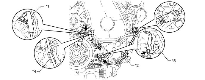
Text in Illustration *1 Clamp *2 Wire Harness Clamp (A) *3 Wire Harness Clamp (B) *4 Protrusion *5 Bracket (Clamp) - -
-
-
INSTALL CAMSHAFT POSITION SENSOR
-
Apply a light coat of engine oil to the O-ring of the camshaft position sensor.
Note
Do not damage the O-ring.
-
Install the camshaft position sensor with the bolt.
- Torque:
- 8.5 N*m { 87 kgf*cm, 75 in.*lbf }
-
-
INSTALL OIL PRESSURE SWITCHING VALVE ASSEMBLY
-
Apply a light coat of engine oil to the O-ring of the oil pressure switching valve.
-
Install the oil pressure switching valve with the bolt.
- Torque:
- 10 N*m { 102 kgf*cm, 7 ft.*lbf }
Note
Do not damage the O-ring.
-
-
INSTALL ENGINE COOLANT TEMPERATURE SENSOR
-
Install a new gasket to the engine coolant temperature sensor.
-
Install the engine coolant temperature sensor.
- Torque:
- 20 N*m { 200 kgf*cm, 14 ft.*lbf }
-
Connect the engine coolant temperature sensor connector.
-
-
INSTALL ENGINE OIL LEVEL SENSOR
-
Install a new gasket and the engine oil level sensor with the 4 bolts.
- Torque:
- 8.0 N*m { 82 kgf*cm, 71 ft.*lbf }
-
-
INSTALL NO. 3 CYLINDER BLOCK INSULATOR
-
Install the No. 3 cylinder block insulator with the clip.
-
-
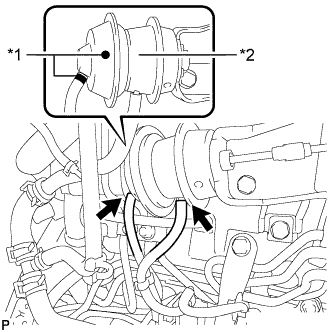
INSTALL THERMOSTAT
-
Install a new gasket to the thermostat.
Note
When installing the gasket to the thermostat, be careful not to deform the gasket. Make sure that the gasket is properly installed to the thermostat as shown in the illustration.
-
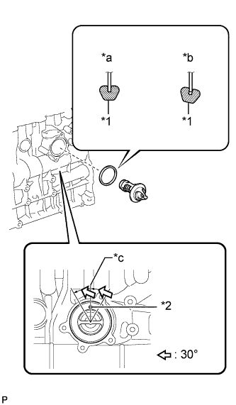
Text in Illustration *1 Gasket *2 Jiggle Valve *a CORRECT *b INCORRECT *c Upward Install the thermostat to the cylinder block with the jiggle valve facing straight upward.
Tech Tips
The jiggle valve may be set within 30° of either side of the prescribed position.
-
-
INSTALL WATER INLET
-
Connect the connector and install the water inlet with the 3 bolts.
- Torque:
- 13 N*m { 133 kgf*cm, 10 ft.*lbf }
-
-
INSTALL NO. 2 CYLINDER BLOCK INSULATOR
-
Install the No. 2 cylinder block insulator to the front No. 1 engine mounting bracket RH.
-
-
INSTALL NO. 1 VACUUM PIPE
-
Install the No. 1 vacuum pipe with the bolt.
- Torque:
- 8.0 N*m { 82 kgf*cm, 70 in.*lbf }
-
-
INSTALL NO. 3 VACUUM TRANSMITTING PIPE SUB-ASSEMBLY
-
Install the No. 3 vacuum transmitting pipe with the bolt.
- Torque:
- 18 N*m { 184 kgf*cm, 13 ft.*lbf }
-
Connect the 2 vacuum hoses.
-
-
INSTALL NO. 2 ENGINE COVER BRACKET
-
Install the No. 2 engine cover bracket with the 2 bolts.
- Torque:
- 23 N*m { 235 kgf*cm, 17 ft.*lbf }
-
-
INSTALL WATER BY-PASS PIPE
-
Temporarily install the No. 2 water by-pass pipe and No. 5 water by-pass pipe with the 3 bolts and 2 nuts.
-
Connect the 3 hoses.
-
Tighten the 2 bolts and 2 nuts.
- Torque:
- 10 N*m { 102 kgf*cm, 7 ft.*lbf }
Note
Tighten the bolts and nus in the order shown in the illustration.
-
Temporarily install the compressor elbow stay with the 2 bolts.
Note
Temporarily install the bolts in the order shown in the illustration.
-
Install the bolt.
- Torque:
- 19 N*m { 194 kgf*cm, 14 ft.*lbf }
-
Tighten the 3 bolts.
- Torque:
- for bolt A
- 23 N*m { 235 kgf*cm, 17 ft.*lbf }
- for bolt B
- 19 N*m { 194 kgf*cm, 14 ft.*lbf }
Text in Illustration Bolt A Bolt B Note
Tighten the bolts in the order shown in the illustration.
-
-
INSTALL ENGINE OIL LEVEL DIPSTICK GUIDE SUB-ASSEMBLY
-
Install the engine oil level dipstick guide with the bolt.
- Torque:
- 8.0 N*m { 82 kgf*cm, 71 in.*lbf }
-
-
INSTALL EXHAUST MANIFOLD WITH TURBOCHARGER
-
Temporarily install a new gasket and the turbocharger sub-assembly with 3 new nuts to the exhaust manifold.
Tech Tips
It is easier to install the turbo oil inlet pipe sub-assembly if the 3 nuts are only loosely installed.
-
Set a new gasket on the engine and install the exhaust manifold with turbocharger and the 8 plate washers with 8 new nuts.
- Torque:
- 40 N*m { 408 kgf*cm, 30 ft.*lbf }
-
Temporarily install the turbo oil inlet pipe sub-assembly.
Tech Tips
Before installing the turbo oil inlet pipe sub-assembly, clean it.
-
Install a new gasket and the turbo oil inlet pipe sub-assembly with the 2 nuts, but only loosely install the nuts.
Note
The notch (narrow part) of the gasket must face the engine.
-
Install a new gasket and the turbo oil inlet pipe sub-assembly with the 2 bolts, but only loosely install the bolts.
Note
The claws of the gasket must face the pipe.
-
Install a new gasket and the turbo oil inlet pipe sub-assembly with the union bolt, but only loosely install the union bolt.
Text in Illustration *1 Gasket - - *a Wide *b Narrow *c Claw - - Outside - - -
Temporarily install the turbocharger stay to the turbocharger sub-assembly and cylinder block sub-assembly with the 2 bolts and a new nut.
-
-
Tighten the 3 nuts of the turbocharger sub-assembly.
- Torque:
- 52 N*m { 530 kgf*cm, 38 ft.*lbf }
-
Tighten the 2 nuts labeled A.
- Torque:
- 13 N*m { 133 kgf*cm, 10 ft.*lbf }
-
Tighten the union bolt labeled B.
- Torque:
- 33 N*m { 337 kgf*cm, 24 ft.*lbf }
-
Tighten the 2 bolts labeled C.
- Torque:
- 12 N*m { 122 kgf*cm, 9 ft.*lbf }
-
Tighten the 2 bolts and nut of the turbocharger stay in the order shown in the illustration.
- Torque:
- 38 N*m { 387 kgf*cm, 28 ft.*lbf }
-
-
INSTALL WIRE HARNESS CLAMP BRACKET
-
Install the wire harness clamp bracket with the bolt.
- Torque:
- 51 N*m { 520 kgf*cm, 38 ft.*lbf }
-
-
CONNECT NO. 3 TURBO WATER HOSE
-
Install the No. 3 turbo water hose to the No. 2 water by-pass pipe and slide the clamp to secure the hose.
-
-
CONNECT NO. 1 TURBO WATER HOSE
-
Type B
Connect the No. 3 turbo water hose to the compressor inlet elbow and slide the clamp to secure the hose.
-
Connect the No. 1 turbo water hose to the No. 2 water by-pass pipe and slide the 2 clamps to secure the hoses.
-
-
CONNECT ENGINE OIL LEVEL DIPSTICK GUIDE SUB-ASSEMBLY
-
Connect the engine oil level dipstick guide to the cylinder block sub-assembly.
-
Install the bolt.
- Torque:
- 8.0 N*m { 82 kgf*cm, 71 in.*lbf }
-
-
INSTALL NO. 1 EXHAUST MANIFOLD HEAT INSULATOR
-
Temporarily install the No. 1 exhaust manifold heat insulator to the exhaust manifold with the 2 bolts.
-
-
INSTALL NO. 1 TURBO INSULATOR
-
Temporarily install the No. 1 turbo insulator to the turbocharger sub-assembly with the 2 bolts.
-
Tighten the 2 bolts of the No. 1 exhaust manifold heat insulator and the 2 bolts of the No. 1 turbo insulator.
- Torque:
- 12 N*m { 122 kgf*cm, 9 ft.*lbf }
-
-
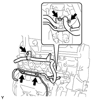
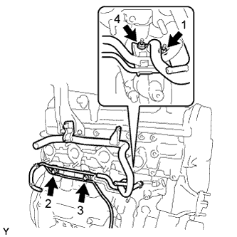
INSTALL VENTILATION PIPE
-
Connect the 2 ventilation hoses and install the ventilation pipe to the cylinder head sub-assembly with the bolt.
- Torque:
- 18 N*m { 184 kgf*cm, 13 ft.*lbf }
-
Type A
Connect the No. 3 turbo water hose and No. 4 turbo water hose to the ventilation pipe.
-
-
INSTALL TURBINE OUTLET ELBOW
-
Temporarily install the turbine outlet elbow to the turbocharger sub-assembly with a new gasket and 3 new nuts.
-
Temporarily install the No. 1 fuel pipe with the 2 bolts.
-
Temporarily install the No. 1 fuel pipe with a new gasket and the union bolt.
-
Text in Illustration *1 No. 4 Water By-pass Pipe *2 No. 12 Water By-pass Hose *3 Turbine Outlet Elbow *4 Gasket *5 No. 1 Fuel Pipe *6 Union Bolt Tighten the 3 nuts of the turbine outlet elbow.
- Torque:
- 30 N*m { 306 kgf*cm, 22 ft.*lbf }
-
Connect the No. 4 water by-pass pipe to the No. 12 water by-pass hose and slide the 2 clamps to secure the hose.
-
Install a new gasket and the union bolt to the turbine outlet elbow.
- Torque:
- 30 N*m { 306 kgf*cm, 22 ft.*lbf }
-
-
INSTALL NO. 11 WATER BY-PASS HOSE
-
Install the No. 11 water by-pass hose to the turbine outlet elbow and slide the 2 clamps to secure the hose.
-
Connect the exhaust fuel addition injector connector.
-
-
INSTALL FUEL PIPE CLAMP
-
Install the fuel pipe clamp to the turbine outlet elbow with the bolt.
- Torque:
- 10 N*m { 102 kgf*cm, 7 in.*lbf }
-
-
INSTALL NO. 2 TURBINE OUTLET ELBOW
-
Install a new gasket and the No. 2 turbine outlet elbow to the turbine outlet elbow with 3 new nuts.
- Torque:
- 30 N*m { 306 kgf*cm, 22 ft.*lbf }
-
-
INSTALL TURBINE OUTLET ELBOW STAY
-
Temporarily install the turbine outlet elbow stay to the No. 2 turbine outlet elbow and cylinder block sub-assembly with the 2 bolts.
-
Tighten the 2 bolts of the turbine outlet elbow stay in the order shown in the illustration.
- Torque:
- 45 N*m { 459 kgf*cm, 33 ft.*lbf }
-
-
INSTALL NO. 2 EXHAUST MANIFOLD HEAT INSULATOR
-
Install the No. 2 exhaust manifold heat insulator to the turbine outlet elbow with the 2 bolts.
- Torque:
- 13 N*m { 133 kgf*cm, 10 ft.*lbf }
-
-
INSTALL NO. 1 FUEL PIPE
-
Text in Illustration *1 No. 2 Fuel Pipe Bolt Union Bolt Temporarily install the No. 1 fuel pipe with the 4 bolts.
-
Temporarily install a new gasket with the union bolt.
-
Tighten the union bolt and 4 bolts in the order shown in the illustration.
- Torque:
- for union bolt
- 30 N*m { 306 kgf*cm, 22 ft.*lbf }
- for bolt
- 6.5 N*m { 66 kgf*cm, 58 in.*lbf }
-
Connect the No. 2 fuel pipe Click here.
-
-
INSTALL NO. 1 COMPRESSOR MOUNTING BRACKET
-
Install the No. 1 compressor mounting bracket with the 5 bolts.
- Torque:
- 21 N*m { 214 kgf*cm, 15 ft.*lbf }
Tech Tips
Firmly press and hold the No. 1 compressor mounting bracket against the cylinder block to eliminate any gaps. Then uniformly tighten the 5 bolts.
-
-
INSTALL NO. 2 IDLE PULLEY ASSEMBLY (w/ Air Conditioning System)
-
Install the spacer, No. 2 idle pulley and pulley plate with the bolt.
- Torque:
- 50 N*m { 510 kgf*cm, 37 ft.*lbf }
-
-
INSTALL IDLE PULLEY ASSEMBLY (w/ Air Conditioning System)
-
Install the spacer, idle pulley and pulley plate with the bolt.
- Torque:
- 50 N*m { 510 kgf*cm, 37 ft.*lbf }
-
-
INSTALL GENERATOR BRACKET
-
Install the generator bracket with the bolt.
- Torque:
- 21 N*m { 214 kgf*cm, 15 ft.*lbf }
-
-
INSTALL GENERATOR ASSEMBLY
-
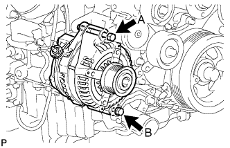
Install the generator with the 2 bolts.
- Torque:
- for bolt A
- 62 N*m { 632 kgf*cm, 46 ft.*lbf }
- for bolt B
- 21 N*m { 214 kgf*cm, 15 ft.*lbf }
-