ENGINE UNIT (w/ DPF) INSPECTION

-
INSPECT INJECTION GEAR BEARING
-
Check that the bearing is not rough or worn.
If necessary, replace the injection gear.
-
-
INSPECT NO. 1 IDLE GEAR OIL CLEARANCE
-
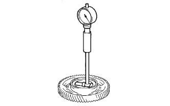
Using a cylinder gauge, measure the inside diameter of the idle gear.
Standard idle gear inside diameter 44.000 to 44.025 mm (1.732 to 1.734 in.) -
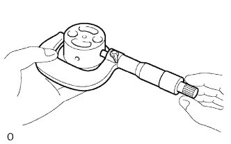
Using a micrometer, measure the diameter of the idle gear shaft.
Standard idle gear shaft diameter 43.955 to 43.990 mm (1.730 to 1.732 in.) -
Subtract the idle gear shaft diameter measurement from the idle gear inside diameter measurement.
Standard oil clearance 0.01 to 0.07 mm (0.000394 to 0.00276 in.) Maximum oil clearance 0.20 mm (0.00787 in.) If the oil clearance is more than the maximum, replace the gear and shaft.
-
-
INSPECT VALVE LIFTER
-
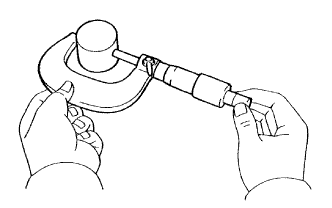
Using a micrometer, measure the lifter diameter.
Standard lifter diameter 30.966 to 30.976 mm (1.219 to 1.220 in.) -
Using a caliper gauge, measure the lifter bore diameter of the cylinder head.
Standard lifter bore diameter 31.000 to 31.021 mm (1.220 to 1.221 in.) -
Measure the oil clearance by subtracting the lifter diameter measurement from the lifter bore diameter measurement.
Standard oil clearance 0.024 to 0.055 mm (0.000945 to 0.00217 in.) Maximum oil clearance 0.095 mm (0.00374 in.) If the oil clearance is more than the maximum, replace the lifter. If necessary, replace the cylinder head.
-
-
INSPECT INTAKE MANIFOLD
-
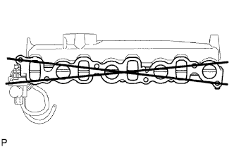
Using a precision straightedge and feeler gauge, measure the warpage of the surface of the intake manifold that contacts the cylinder head.
Maximum warpage 0.1 mm (0.00394 in.) If the warpage is more than the maximum, replace the intake manifold.
-
-
INSPECT EXHAUST MANIFOLD
-
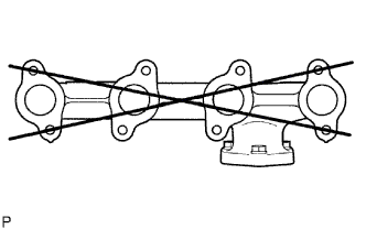
Using a precision straightedge and feeler gauge, measure the warpage of the surface of the exhaust manifold that contacts the cylinder head.
Maximum warpage 0.2 mm (0.00787 in.) If the warpage is more than the maximum, replace the exhaust manifold.
-
-
INSPECT CAMSHAFT
-
Inspect the circle runout.
-
Place the camshaft on V-blocks.
-
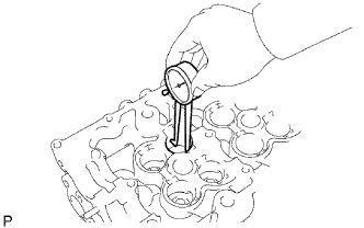
Using a dial indicator, measure the circle runout at the center journal.
Maximum circle runout 0.03 mm (0.00118 in.) If the circle runout is more than the maximum, replace the camshaft.
-
-
Inspect the cam lobe height.
-
Using a micrometer, measure the cam lobe height.
Standard cam lobe height 46.99 to 47.09 mm (1.850 to 1.854 in.) Minimum cam lobe height 46.57 mm (1.833 in.) If the cam lobe height is less than the minimum, replace the camshaft.
-
-
Inspect the diameter of the camshaft journal.
-
Using a micrometer, measure the diameter of the camshaft journal for the camshaft bearing.
Standard diameter 27.969 to 27.985 mm (1.101 to 1.102 in.) If the diameter is not as specified, check the oil clearance.
-
-
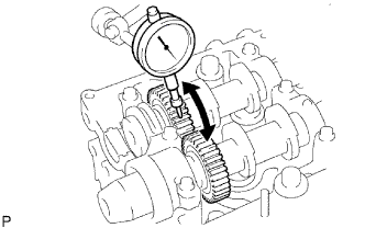
Using a dial indicator, measure the backlash.
-
Install the 2 camshafts.
-
Using a dial indicator, measure the backlash.
Standard backlash 0.035 to 0.089 mm (0.00138 to 0.00350 in.) Maximum backlash 0.189 mm (0.00744 in.) If the backlash is more than the maximum, replace the 2 camshafts.
-
Remove the 2 camshafts.
-
-
-
INSPECT NO. 2 CAMSHAFT
-
Inspect the circle runout.
-
Place the camshaft on V-blocks.
-
Using a dial indicator, measure the circle runout at the center journal.
Maximum circle runout 0.03 mm (0.00118 in.) If the circle runout is more than the maximum, replace the camshaft.
-
-
Inspect the cam lobe height.
-
Using a micrometer, measure the cam lobe height.
Standard cam lobe height 48.31 to 48.41 mm (1.902 to 1.906 in.) Minimum cam lobe height 48.16 mm (1.896 in.) If the cam lobe height is less than the minimum, replace the camshaft.
-
-
Inspect the diameter of the camshaft journal.
-
Using a micrometer, measure the diameter of the camshaft journal for the camshaft bearing.
Standard diameter 27.969 to 27.985 mm (1.101 to 1.102 in.) If the diameter is not as specified, check the oil clearance.
-
-
-
INSPECT CAMSHAFT OIL CLEARANCE
-
Clean the bearing caps and journals.
-
Check the bearings for flaking and scoring.
If the bearings are damaged, replace the bearing caps and cylinder head as a set.
-
Place the camshaft on the cylinder head.
-
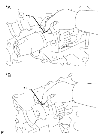
Text in Illustration *A Intake Side *B Exhaust Side *1 Plastigage Lay a strip of Plastigage across each of the journals.
-
Install the bearing caps.
Note
Do not turn the camshaft.
-
Remove the bearing caps.
-
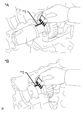
Text in Illustration *A Intake Side *B Exhaust Side *1 Plastigage Measure the Plastigage at its widest point.
Standard oil clearance 0.025 to 0.062 mm (0.000984 to 0.00244 in.) Maximum oil clearance 0.1 mm (0.00394 in.) If the oil clearance is more than the maximum, replace the camshaft. If necessary, replace the bearing caps and cylinder head as a set.
-
Completely remove the Plastigage.
-
Remove the camshaft.
-
-
INSPECT CAMSHAFT THRUST CLEARANCE
-
Install the camshaft.
-
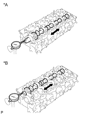
Text in Illustration *A Intake Side *B Exhaust Side Using a dial indicator, measure the thrust clearance while moving the camshaft back and forth.
Standard thrust clearance 0.035 to 0.185 mm (0.00138 to 0.0728 in.) Maximum thrust clearance 0.25 mm (0.00984 in.) If the thrust clearance is more than the maximum, replace the camshaft. If necessary, replace the bearing caps and cylinder head as a set.
-
Remove the camshaft.
-
-
INSPECT CYLINDER HEAD SET BOLT
-
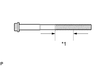
Text in Illustration *1 Measuring Area Using a vernier caliper, measure the diameter of the most elongated threads in the measurement area.
Measuring area 33 mm (1.30 in.) Standard outside diameter 11.76 to 11.97 mm (0.463 to 0.471 in.) Minimum outside diameter 11.6 mm (0.457 in.) Tech Tips
If a visual check reveals no excessively thin areas, check the center of the bolt (see illustration) and find the area that has the smallest diameter.
If the diameter is less than the minimum, replace the cylinder head set bolt.
-