-
When replacing the injectors (including shuffling the injectors between the cylinders), common rail or cylinder head, it is necessary to replace the injection pipes with new ones.
-
When replacing the fuel supply pump, common rail, cylinder block, cylinder head, cylinder head gasket or timing gear case, it is necessary to replace the fuel inlet pipe with a new one.
- Click here
REMOVE GENERATOR ASSEMBLY
-
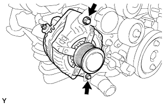
Remove the 2 bolts and generator.
-
- Click here
REMOVE GENERATOR BRACKET
-
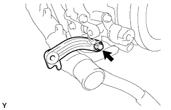
Remove the bolt and generator bracket.
-
- Click here
REMOVE IDLE PULLEY ASSEMBLY (w/ Air Conditioning System)
-
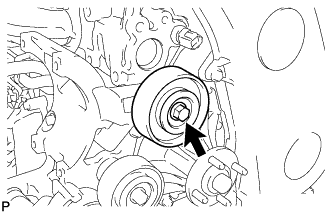
Remove the bolt, pulley plate, idle pulley and spacer.
-
- Click here
REMOVE NO. 2 IDLE PULLEY ASSEMBLY (w/ Air Conditioning System)
-
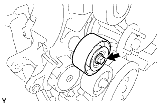
Remove the bolt, pulley plate, No. 2 idle pulley and spacer.
-
- Click here
REMOVE NO. 1 COMPRESSOR MOUNTING BRACKET
-
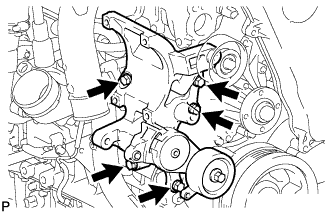
Remove the 5 bolts and No. 1 compressor mounting bracket.
-
- Click here
REMOVE NO. 1 FUEL PIPE
-
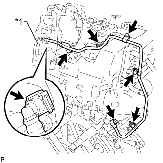
Disconnect the No. 2 fuel pipe (Click here).
Table 1. Text in Illustration *1 No. 2 Fuel Pipe -
Remove the 4 bolts, union bolt, gasket and No. 1 fuel pipe.
-
- Click here
REMOVE NO. 2 EXHAUST MANIFOLD HEAT INSULATOR
-
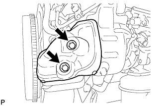
Remove the 2 bolts and No. 2 exhaust manifold heat insulator from the turbine outlet elbow.
-
- Click here
REMOVE TURBINE OUTLET ELBOW STAY
-
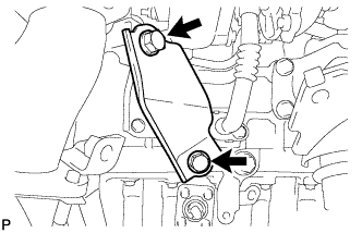
Remove the 2 bolts and turbine outlet elbow stay from the No. 2 turbine outlet elbow and cylinder block sub-assembly.
-
- Click here
REMOVE NO. 2 TURBINE OUTLET ELBOW
-
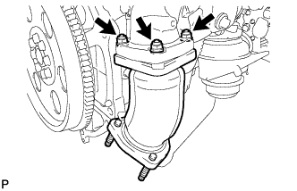
Remove the 3 nuts, No. 2 turbine outlet elbow and gasket from the turbine outlet elbow.
-
- Click here
REMOVE FUEL PIPE CLAMP
-
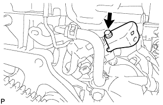
Remove the bolt and fuel pipe clamp from the turbine outlet elbow.
-
- Click here
REMOVE NO. 11 WATER BY-PASS HOSE
-
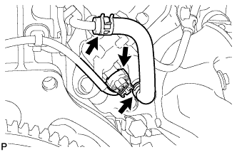
Disconnect the exhaust fuel addition injector connector.
-
Slide the 2 clamps and remove the No. 11 water by-pass hose from the turbine outlet elbow.
-
- Click here
REMOVE TURBINE OUTLET ELBOW
-
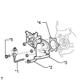
Remove the union bolt and gasket from the turbine outlet elbow.
Table 2. Text in Illustration *1 No. 4 Water By-pass Pipe *2 No. 12 Water By-pass Hose *3 Turbine Outlet Elbow *4 Gasket *5 Union Bolt -
Slide the clamp and remove the No. 4 water by-pass pipe from the No. 12 water by-pass hose.
-
Remove the 3 nuts, turbine outlet elbow and gasket from the turbocharger sub-assembly.
-
- Click here
REMOVE VENTILATION PIPE
-
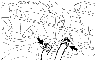
Type A
Slide the 2 clamps and disconnect the No. 3 turbo water hose and No. 4 turbo water hose from the ventilation pipe.
-
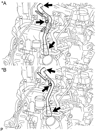
Remove the bolt and disconnect the 2 ventilation hoses and ventilation pipe from the cylinder head sub-assembly.
Table 3. Text in Illustration *A Type A *B Type B
-
- Click here
REMOVE NO. 1 TURBO INSULATOR
-
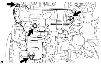
Remove the 2 bolts and No. 1 turbo insulator from the turbocharger sub-assembly.
-
- Click here
REMOVE NO. 1 EXHAUST MANIFOLD HEAT INSULATOR
-
Remove the 2 bolts and No. 1 exhaust manifold heat insulator from the exhaust manifold.
-
- Click here
DISCONNECT ENGINE OIL LEVEL DIPSTICK GUIDE SUB-ASSEMBLY
-
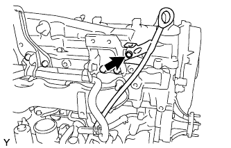
Remove the bolt.
-
Disconnect the engine oil level dipstick guide from the cylinder block sub-assembly.
-
- Click here
DISCONNECT NO. 1 TURBO WATER HOSE
-
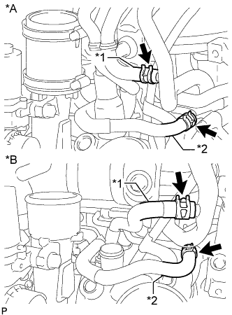
Slide the 2 clamps and disconnect the No. 1 turbo water hose from the No. 2 water by-pass pipe.
Table 4. Text in Illustration *A Type A *B Type B *1 No. 1 Turbo Water Hose *2 No. 3 Turbo Water Hose -
Type B
Slide the clamp and disconnect the No. 3 turbo water hose from the compressor inlet elbow.
-
- Click here
DISCONNECT NO. 3 TURBO WATER HOSE
-
Slide the clamp and remove the No. 3 turbo water hose from the No. 2 water by-pass pipe.
-
- Click here
REMOVE TURBOCHARGER STAY
-
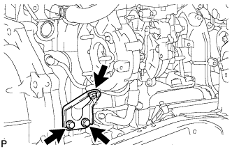
Remove the 2 bolts, nut and turbocharger stay from the turbocharger sub-assembly and cylinder block.
-
- Click here
REMOVE WIRE HARNESS CLAMP BRACKET
-
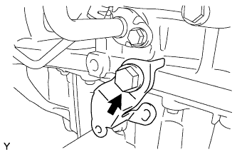
Remove the bolt and wire harness clamp bracket from the cylinder block.
-
- Click here
REMOVE TURBO OIL INLET PIPE SUB-ASSEMBLY
-
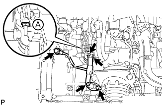
Remove the 2 bolts, 2 nuts, union bolt, turbo oil inlet pipe sub-assembly and 3 gaskets.
Note:Do not loosen the nut labeled A in the illustration.
-
- Click here
REMOVE EXHAUST MANIFOLD WITH TURBOCHARGER
-
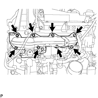
Remove the 8 nuts and 8 plate washers from the exhaust manifold with turbocharger sub-assembly.
-
Remove the exhaust manifold with turbocharger sub-assembly and gasket.
-
- Click here
REMOVE ENGINE OIL LEVEL DIPSTICK GUIDE SUB-ASSEMBLY
-
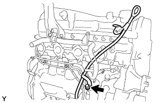
Remove the bolt and engine oil level dipstick guide.
-
- Click here
REMOVE COMPRESSOR ELBOW STAY
-
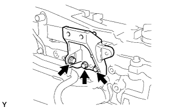
Remove the 3 bolts and compressor elbow stay.
-
- Click here
REMOVE NO. 5 WATER BY-PASS PIPE SUB-ASSEMBLY
-
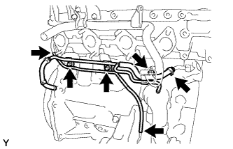
Disconnect the 3 hoses.
-
Remove the 2 bolts, nut and No. 5 water by-pass pipe.
-
- Click here
REMOVE NO. 2 WATER BY-PASS PIPE SUB-ASSEMBLY
-
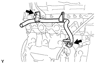
Remove the bolt, nut and No. 2 water by-pass pipe.
-
- Click here
REMOVE NO. 2 ENGINE COVER BRACKET
-
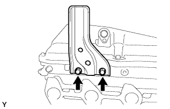
Remove the 2 bolts and No. 2 engine cover bracket.
-
- Click here
REMOVE NO. 3 VACUUM TRANSMITTING PIPE SUB-ASSEMBLY
-
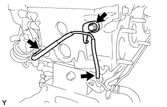
Disconnect the 2 vacuum hoses.
-
Remove the bolt and No. 3 vacuum transmitting pipe.
-
- Click here
REMOVE NO. 1 VACUUM PIPE
-
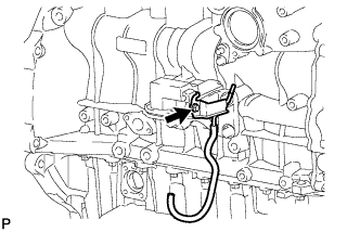
Remove the bolt and No. 1 vacuum pipe.
-
- Click here
REMOVE NO. 2 CYLINDER BLOCK INSULATOR
-
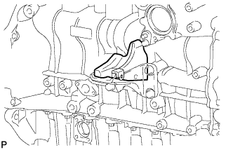
Remove the No. 2 cylinder block insulator from the front No. 1 engine mounting bracket RH.
-
- Click here
REMOVE WATER INLET
-
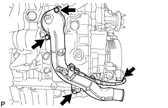
Disconnect the connector and remove the 3 bolts and water inlet.
-
- Click here
REMOVE THERMOSTAT
-
Remove the thermostat.
-
Remove the gasket from the thermostat.
-
- Click here
REMOVE NO. 3 CYLINDER BLOCK INSULATOR
-
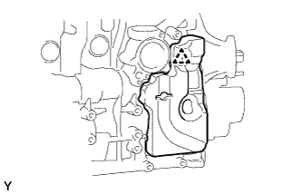
Detach the clip and remove the No. 3 cylinder block insulator.
-
- Click here
REMOVE ENGINE OIL LEVEL SENSOR
-
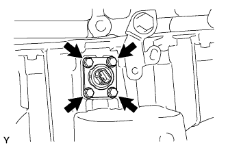
Remove the 4 bolts and engine oil level sensor.
-
Cut away part of the gasket and remove the gasket from the engine oil level sensor.
Tip:Remove only the outer part of the gasket.
-
- Click here
REMOVE ENGINE COOLANT TEMPERATURE SENSOR
-
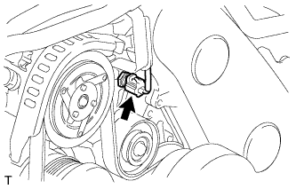
Disconnect the engine coolant temperature sensor connector.
-
Remove the engine coolant temperature sensor.
-
Remove the gasket from the engine coolant temperature sensor.
-
- Click here
REMOVE OIL PRESSURE SWITCHING VALVE ASSEMBLY
-
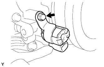
Remove the bolt and oil pressure switching valve.
-
- Click here
REMOVE CAMSHAFT POSITION SENSOR
-
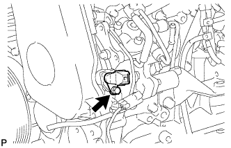
Remove the bolt and camshaft position sensor.
-
- Click here
REMOVE CRANKSHAFT POSITION SENSOR
-
Detach the 2 wire harness clamps (A, B).
-
Disconnect the crankshaft position sensor connector.
-
Detach the crankshaft position sensor connector from the No. 1 vacuum transmitting pipe.
-
Remove the clamp.
Note:
-
Make sure that no portion of the clamp remains in the clamp installation hole. If there is any portion of the clamp remaining, remove it.
-
Do not reuse the clamp.
-
-
Remove the bolt and bracket (clamp).
-
Remove the bolt and crankshaft position sensor.
-
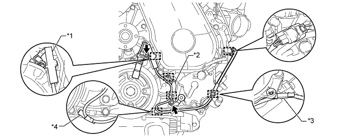
Detach the 2 wire harness clamps from the bracket (clamp).
Table 5. Text in Illustration *1 Clamp *2 Bracket (Clamp) *3 Wire Harness Clamps (A) *4 Wire Harness Clamps (B)
-
- Click here
REMOVE VACUUM PUMP ASSEMBLY
-
Remove the bolt and bracket.
-
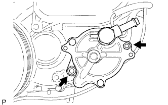
Remove the 2 nuts, vacuum pump and 2 O-rings.
-
- Click here
REMOVE VANE PUMP ASSEMBLY
-
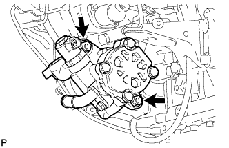
Remove the 2 nuts, vane pump and O-ring.
-
- Click here
REMOVE NO. 1 TIMING BELT COVER
-
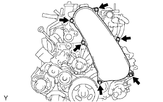
Remove the 6 bolts, 6 washers and timing belt cover.
-
- Click here
REMOVE TIMING BELT
-
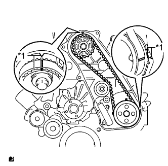
Turn the crankshaft clockwise and align the timing marks as shown in the illustration.
Table 6. Text in Illustration *1 Timing Mark Tip:If reusing the timing belt, place matchmarks on the timing belt so that it can be installed exactly as before.
-
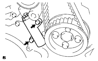
Uniformly loosen and remove the 2 bolts and No. 1 timing belt tensioner.
-
Remove the timing belt.
Tip: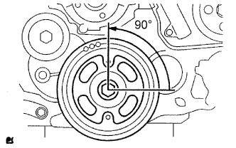
-
If turning the camshaft while the timing belt is removed, turn the crankshaft 90° counterclockwise as shown in the illustration.
-
When installing the timing belt, turn the camshaft to align the timing marks and then turn the crankshaft clockwise to align the timing marks.
-
-
- Click here
REMOVE NO. 1 TIMING BELT IDLER SUB-ASSEMBLY
Note:When inspecting the No. 1 timing belt idler, do not remove it unless absolutely necessary.
-
Using a 10 mm hexagon wrench, remove the bolt, No. 1 timing belt idler and washer.
-
- Click here
REMOVE CRANKSHAFT PULLEY
-
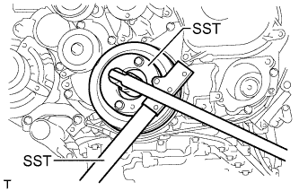
Using SST, hold the crankshaft pulley and loosen the pulley bolt.
09213-58014 09330-00021 -
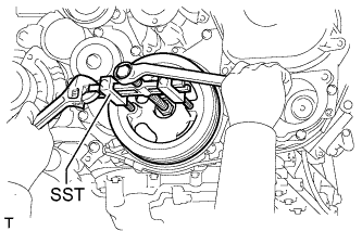
Using SST, remove the pulley bolt and crankshaft pulley.
09950-50013 09951-05010 09952-05010 09953-05020 09954-05021
-
- Click here
REMOVE DIESEL THROTTLE BODY ASSEMBLY
-
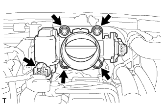
Disconnect the throttle control motor connector.
-
Remove the 2 bolts, 2 nuts, diesel throttle body and gasket.
-
- Click here
REMOVE MANIFOLD ABSOLUTE PRESSURE SENSOR
-
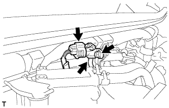
Disconnect the manifold absolute pressure sensor connector and vacuum hose.
-
Remove the bolt and manifold absolute pressure sensor.
-
- Click here
REMOVE EMISSION CONTROL VALVE BRACKET
-
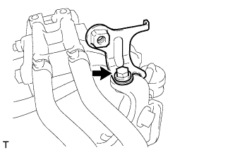
Remove the bolt and emission control valve bracket.
-
- Click here
REMOVE THROTTLE BODY BRACKET
-
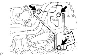
Remove the 3 bolts and throttle body bracket.
-
- Click here
REMOVE NO. 1 GAS FILTER
-
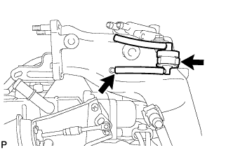
Disconnect the vacuum hose and remove the No. 1 gas filter from the gas filter bracket.
-
- Click here
REMOVE GAS FILTER BRACKET
-
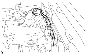
Detach the clamp and disconnect the wire harness.
-
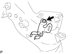
Remove the bolt and gas filter bracket.
-
- Click here
REMOVE NO. 2 CYLINDER HEAD COVER SUB-ASSEMBLY
-
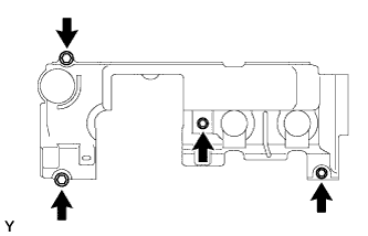
Remove the 4 bolts and No. 2 cylinder head cover sub-assembly.
-
- Click here
REMOVE NO. 1 VACUUM TRANSMITTING PIPE
-
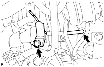
Disconnect the vacuum hose from the intake manifold.
-
Remove the bolt and No. 1 vacuum transmitting pipe.
-
- Click here
REMOVE MANIFOLD STAY WITH VACUUM SWITCHING VALVE
-
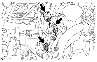
Disconnect the 3 vacuum switching valve connectors.
-
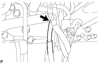
Disconnect the No. 1 vacuum transmitting hose.
-
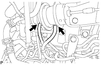
Disconnect the 2 No. 2 vacuum transmitting hoses from the No. 2 EGR valve.
-
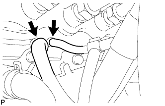
Disconnect the No. 1 vacuum transmitting hose and No. 4 vacuum transmitting hose.
-
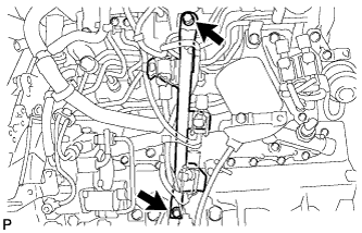
Remove the 2 bolts and manifold stay with vacuum switching valve.
-
- Click here
REMOVE WATER BY-PASS HOSE
-
Detach the 4 water by-pass hose clamps.
-
Disconnect the No. 7 water by-pass hose labeled A in the illustration.
-
Disconnect the No. 4 water by-pass hose labeled B in the illustration.
-
Disconnect the No. 3 water by-pass hose labeled C in the illustration.
-
Disconnect the No. 8 water by-pass hose labeled D in the illustration.
-
Disconnect the No. 6 water by-pass hose labeled E in the illustration.
-
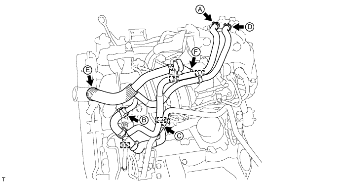
Disconnect the No. 5 water by-pass hose labeled F in the illustration.
-
- Click here
REMOVE FUEL INLET PIPE SUB-ASSEMBLY
-
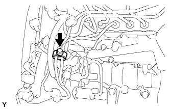
Remove the bolt and No. 2 injection pipe clamp.
-
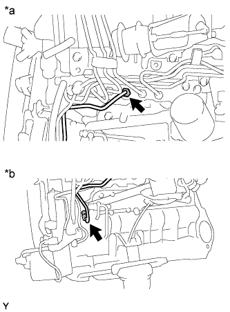
Using a 17 mm union nut wrench, loosen the union nuts and remove the fuel inlet pipe.
Table 7. Text in Illustration *a Common Rail Side *b Fuel Supply Pump Side
-
- Click here
REMOVE WIRING HARNESS CLAMP BRACKET
-
Disconnect the glow plug connector.
-
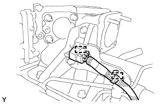
Detach the 2 wire harness clamps and disconnect the glow plug connector from the wiring harness clamp bracket.
-
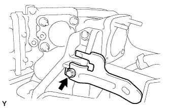
Remove the bolt and wiring harness clamp bracket.
-
- Click here
REMOVE NO. 1, NO. 2 AND NO. 3 INJECTION PIPE SUB-ASSEMBLY
Note:
-
After removing the injection pipe, cover the outlets on the common rail with tape to keep out foreign matter.
-
After removing the injection pipe, put it in a plastic bag to prevent foreign matter from contaminating its injector inlet.
-
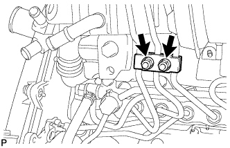
Remove the 2 nuts and No. 3 injection pipe clamp.
-
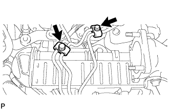
Remove the 2 bolts and 2 No. 2 injection pipe clamps.
-
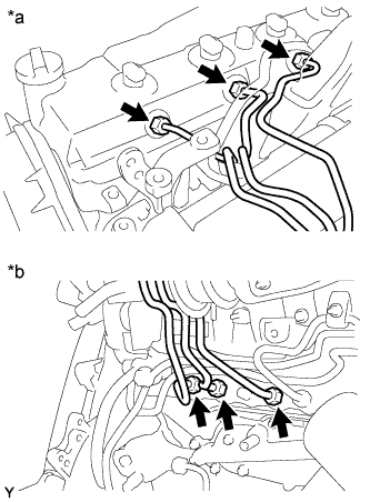
Using a 17 mm union nut wrench, loosen the union nuts and remove the No. 1, No. 2 and No. 3 injection pipes.
Table 8. Text in Illustration *a Injector Side *b Common Rail Side
-
- Click here
REMOVE AIR CONNECTOR STAY
-
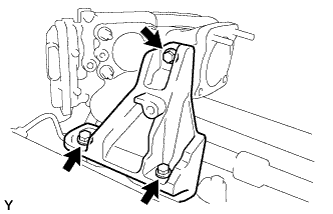
Remove the 3 bolts and air connector stay.
-
- Click here
REMOVE ELECTRIC EGR CONTROL VALVE ASSEMBLY WITH NO. 2 EGR VALVE AND EGR COOLER
-
Remove the 2 nuts, the 5 bolts and the electric EGR control valve with No. 2 EGR valve and EGR cooler.
-
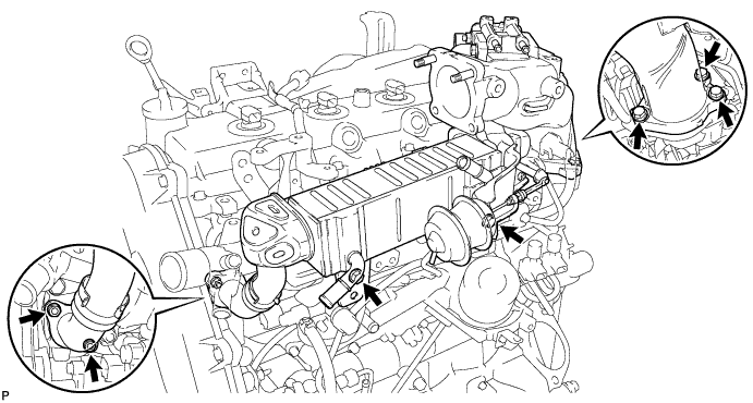
Remove the 2 gaskets from the cylinder head and intake manifold.
-
- Click here
REMOVE ELECTRIC EGR CONTROL VALVE ASSEMBLY
-
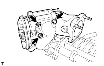
Remove the 2 nuts, bolt and intake air connector together with the electric EGR control valve.
-
Remove the electric EGR control valve and 2 gaskets from the intake air connector.
-
- Click here
REMOVE EGR VALVE ADAPTER
-
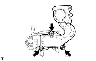
Using a 6 mm hexagon wrench, remove the 3 hexagon bolts, 3 plate washers, EGR valve adapter and gasket.
-
- Click here
REMOVE NO. 2 EGR VALVE ASSEMBLY
-
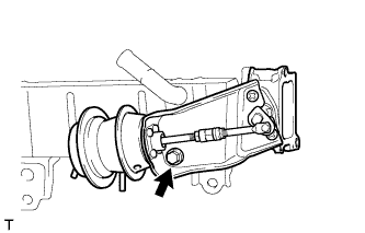
Remove the bolt, No. 2 EGR valve and gasket.
-
- Click here
REMOVE EGR COOLER INSULATOR
-
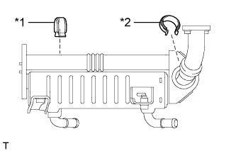
Remove the 2 EGR cooler insulators from the EGR cooler.
Table 9. Text in Illustration *1 No. 2 EGR Cooler Insulator *2 No. 1 EGR Cooler Insulator
-
- Click here
REMOVE NO. 4 INJECTION PIPE SUB-ASSEMBLY
-
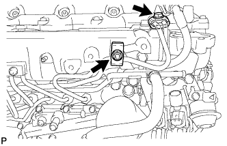
Remove the bolt, nut and 2 No. 2 injection pipe clamps.
-
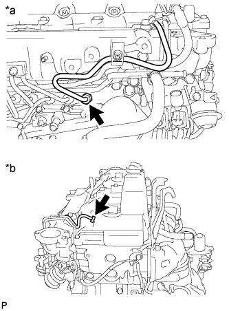
Using a 17 mm union nut wrench, loosen the union nuts and remove the No. 4 injection pipe sub-assembly.
Table 10. Text in Illustration *a Common Rail Assembly Side *b Injector Assembly Side
-
- Click here
REMOVE NO. 2 FUEL PIPE
-
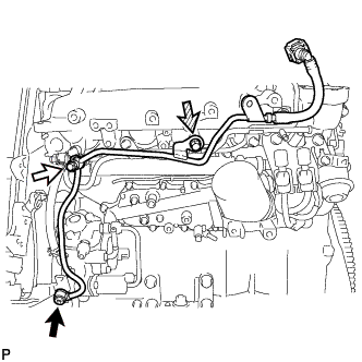
Using a 6 mm hexagon wrench, remove the union bolt and gasket.
Table 11. Text in Illustration 
Union Bolt 
Fuel Check Valve 
Bolt -
Remove the fuel check valve and gasket.
-
Remove the bolt and No. 2 fuel pipe.
-
- Click here
REMOVE NO. 3 NOZZLE LEAKAGE PIPE
-
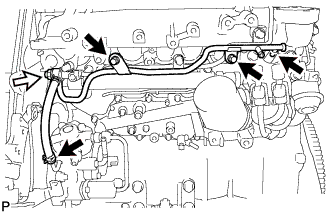
Disconnect the 2 fuel hoses.
Table 12. Text in Illustration Fuel Check Valve -
Remove the 2 bolts.
-
Remove the fuel check valve, gasket and No. 3 nozzle leakage pipe.
-
- Click here
REMOVE NO. 2 NOZZLE LEAKAGE PIPE ASSEMBLY
-
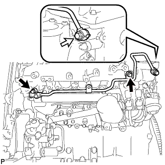
Remove the 2 bolts.
Table 13. Text in Illustration Union Bolt -
Remove the union bolt, gasket and No. 2 nozzle leakage pipe assembly.
-
- Click here
REMOVE VACUUM CONTROL VALVE SET
-
Disconnect the 2 vacuum switching valve connectors.
-
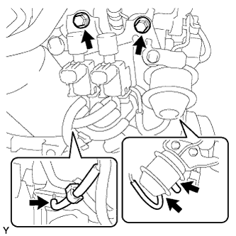
Disconnect the 3 vacuum hoses, and then remove the 2 bolts and vacuum control valve set.
-
- Click here
REMOVE INTAKE PIPE STAY
-
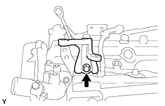
Remove the bolt and intake pipe stay.
-
- Click here
REMOVE INTAKE MANIFOLD INSULATOR
-
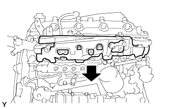
Remove the intake manifold insulator.
-
- Click here
REMOVE INTAKE MANIFOLD
-
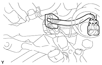
Detach the sensor wire connector clamp from the intake manifold.
-
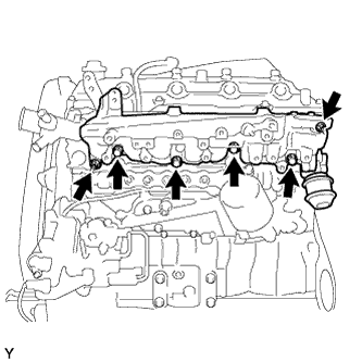
Remove the 2 nuts, 4 bolts, intake manifold and gasket.
-
- Click here
REMOVE NO. 1 GLOW PLUG CONNECTOR
-
Disconnect the No. 1 glow plug connector from the wire harness.
-
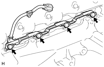
Remove the 4 screw grommets.
-
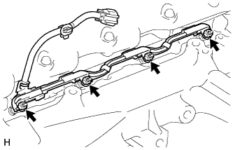
Remove the 4 nuts and No. 1 glow plug connector.
-
-
Click here
REMOVE NO. 1 INTAKE MANIFOLD INSULATOR
-
Click here
REMOVE GLOW PLUG ASSEMBLY
-
Using a 12 mm deep socket wrench, remove the 4 glow plugs.
-
- Click here
REMOVE OIL FILTER SUB-ASSEMBLY
-
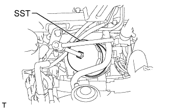
Using SST, remove the oil filter.
09228-07501
-
- Click here
REMOVE COMMON RAIL ASSEMBLY
-
Disconnect the pressure discharge valve connector.
-
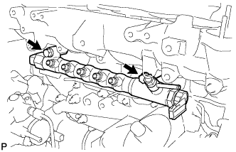
Remove the 2 bolts and common rail assembly.
Note:Do not remove the pressure discharge valve or fuel pressure sensor.
-
- Click here
REMOVE NO. 2 INTAKE MANIFOLD INSULATOR
-
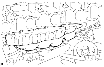
Remove the No. 2 intake manifold insulator.
-
-
Click here
REMOVE INJECTION PUMP INSULATOR
- Click here
REMOVE NO. 1 INJECTION PUMP PROTECTOR
-
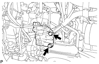
Remove the 2 bolts and No. 1 injection pump protector.
-
- Click here
REMOVE FUEL SUPPLY PUMP ASSEMBLY
-
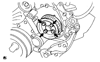
Remove the 4 bolts indicated by the arrows in the illustration.
-
Remove the No. 2 camshaft timing pulley flange and pump drive shaft pulley.
-
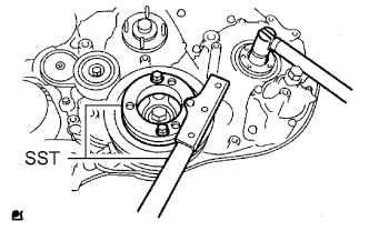
Remove the set nut and O-ring while holding the crankshaft pulley using SST.
09213-58014 09330-00021 -
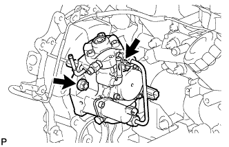
Loosen the 2 nuts.
-
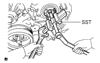
Using SST, disconnect the fuel supply pump from the injection gear.
09950-50013 09951-05010 09952-05010 09953-05020 09954-05021 Note:Apply lubricant to the threads and tip of SST (center bolt) before using it.
-
Remove the 2 nuts and fuel supply pump.
Note:
-
Do not hold or carry the fuel supply pump by the pipe.
-
The fuel supply pump must be kept horizontal.
-
-
Remove the O-ring.
-
- Click here
REMOVE WATER OUTLET
-
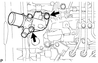
Remove the 2 bolts, gasket and water outlet.
-
- Click here
REMOVE NO. 2 VACUUM TRANSMITTING PIPE SUB-ASSEMBLY
-
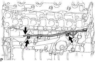
Disconnect the vacuum hose.
-
Remove the 2 nuts and No. 2 vacuum transmitting pipe.
-
- Click here
REMOVE OIL COOLER COVER SUB-ASSEMBLY
-
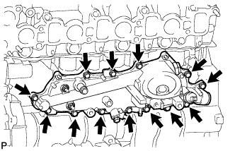
Remove the 13 bolts and oil cooler cover.
-
- Click here
REMOVE NO. 1 VACUUM TRANSMITTING PIPE SUB-ASSEMBLY
-
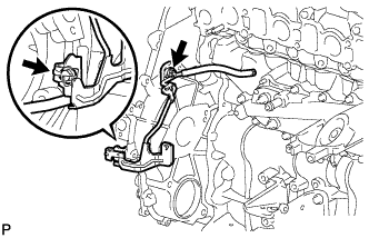
Remove the bolt, nut and No. 1 vacuum transmitting pipe.
-
- Click here
REMOVE NO. 1 OIL PAN COVER SUB-ASSEMBLY
-
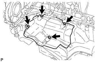
Remove the 4 bolts and No. 1 oil pan cover.
-
- Click here
REMOVE FRONT NO. 1 ENGINE MOUNTING BRACKET
-
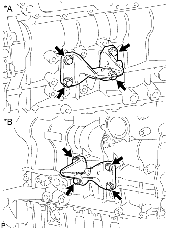
Remove the 8 bolts and 2 front No. 1 engine mounting brackets.
Table 14. Text in Illustration *A for LH Side *B for RH Side
-