ENGINE UNIT DISASSEMBLY

-
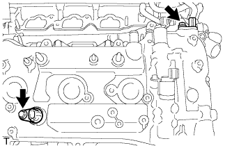
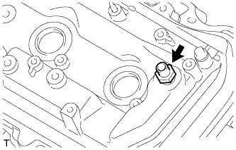
REMOVE ENGINE OIL PRESSURE SWITCH ASSEMBLY
-
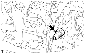
Using a 24 mm deep socket wrench, remove the oil pressure switch.
-
-
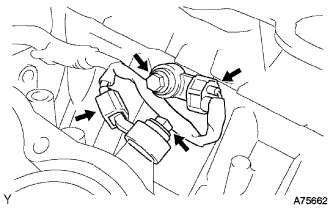
REMOVE ENGINE COOLANT TEMPERATURE SENSOR
-
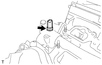
Using a 19 mm deep socket wrench, remove the sensor.
-
Remove the gasket from the sensor.
-
-
REMOVE CYLINDER BLOCK WATER DRAIN COCK SUB-ASSEMBLY
-
Remove the water drain cock plug from the water drain cock.
-
Remove the water drain cock from the cylinder block.
-
-
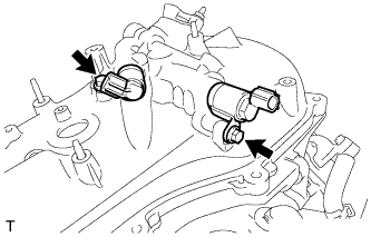
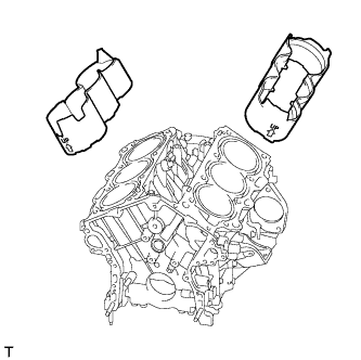
REMOVE VVT SENSOR
-
LH:
Remove the 2 bolts and 2 VVT sensors.
-
RH:
Remove the 2 bolts and 2 VVT sensors.
-
-
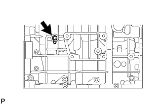
REMOVE CRANKSHAFT POSITION SENSOR
-
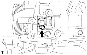
Remove the bolt and crankshaft position sensor.
-
-
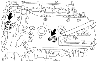
REMOVE CAMSHAFT TIMING OIL CONTROL VALVE ASSEMBLY RH
-
LH:
Remove the 2 bolts and 2 oil control valves.
-
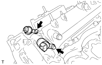
RH:
Remove the 2 bolts and 2 oil control valves.
-
-
REMOVE OIL FILLER CAP HOUSING
-
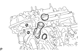
Remove the oil filler cap.
-
Remove the 2 nuts, oil filler cap housing and gasket.
-
-
REMOVE NO. 1 OIL PIPE
-
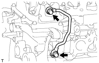
Remove the 2 oil pipe unions, oil control valve filter LH, 3 gaskets and No. 1 oil pipe.
Note
Do not touch the mesh when removing the oil control valve filter.
-
-
REMOVE NO. 2 OIL PIPE
-
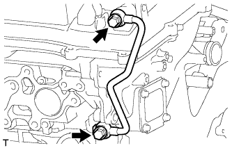
Remove the 2 oil pipe unions, oil control valve filter RH, 3 gaskets and No. 2 oil pipe.
Note
Do not touch the mesh when removing the oil control valve filter.
-
-
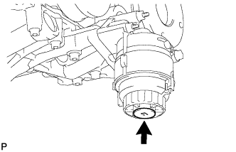
REMOVE OIL FILTER ELEMENT
-
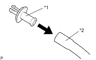
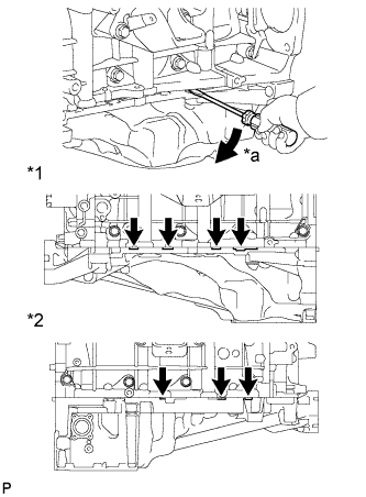
Text in Illustration *1 Pipe *2 Hose Connect a hose with an inside diameter of 15 mm (0.591 in.) to the pipe.
-
Remove the oil filter drain plug.
-
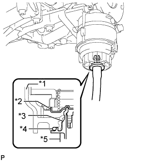
Text in Illustration *1 Cap *2 Valve *3 Pipe *4 O-Ring *5 Hose Install the pipe to the oil filter cap.
Tech Tips
Use a container to catch the draining oil.
Note
If the O-ring is removed with the drain plug, install the O-ring together with the pipe.
-
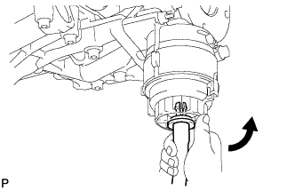
Check that oil is drained from the oil filter. Then, disconnect the pipe and remove the O-ring as shown in the illustration.
-
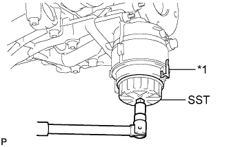
Text in Illustration *1 Oil Filter Bracket Clip Using SST, remove the oil filter cap.
- SST
- 09228-06501
Note
Do not remove the oil filter bracket clip.
-
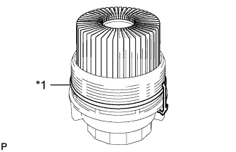
Text in Illustration *1 O-Ring Remove the oil filter element and O-ring from the oil filter cap.
Note
Be sure to remove the O-ring (for the cap) by hand, without using any tools, to prevent damage to the groove for the O-ring in the cap.
-
-
REMOVE OIL FILTER BRACKET
-
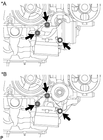
Text in Illustration *A w/ Oil Cooler *B w/o Oil Cooler Remove the 2 nuts, bolt, oil filter bracket and gasket.
-
-
REMOVE WATER INLET HOUSING
-
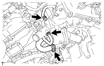
Disconnect the 3 water by-pass hoses.
-
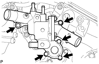
Remove the 5 bolts and water inlet housing.
-
Remove the O-ring and gasket from the water outlet pipe and water pump.
-
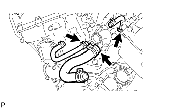
Remove the 3 water by-pass hoses.
-
-
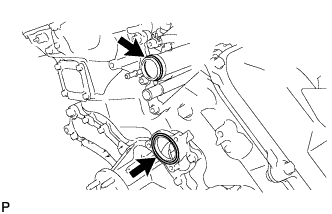
REMOVE REAR WATER BY-PASS JOINT
-
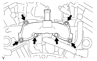
Remove the 2 bolts, 4 nuts, rear water by-pass joint and 2 gaskets.
-
Remove the O-ring from the No. 1 water outlet pipe.
-
-
REMOVE SPARK PLUG
-
Remove the 6 spark plugs.
-
-
REMOVE PCV VALVE SUB-ASSEMBLY
-
Remove the PCV valve hose.
-
Remove the PCV valve.
-
-
REMOVE CRANKSHAFT PULLEY
-
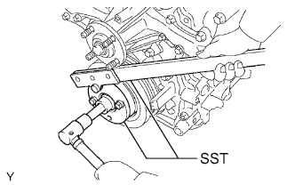
Using SST, hold the crankshaft pulley and loosen the pulley bolt. Continue to loosen the bolt until only 2 or 3 threads are screwed into the crankshaft.
- SST
- 09213-54015 ( 91651-60855 )
- 09330-00021
-
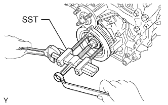
Using the pulley set bolt and SST, remove the crankshaft pulley and pulley bolt.
- SST
- 09950-50013 ( 09951-05010, 09952-05010, 09953-05020, 09954-05031 )
-
-
REMOVE CYLINDER HEAD COVER SUB-ASSEMBLY LH
-
Remove the 12 bolts, seal washer, cylinder head cover and gasket.
Tech Tips
Make sure the removed parts are returned to the same places they were removed from.
-
Remove the 3 gaskets.
-
-
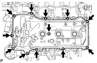
REMOVE CYLINDER HEAD COVER SUB-ASSEMBLY
-
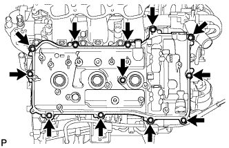
Remove the 12 bolts, seal washer, cylinder head cover and gasket.
Tech Tips
Make sure the removed parts are returned to the same places they were removed from.
-
Remove the 3 gaskets.
-
-
REMOVE SPARK PLUG TUBE GASKET
-
Bend the ventilation baffle plate claws on the cylinder head cover to an angle of 90° or more.
Text in Illustration 
Pry -
Remove the 6 spark plug tube gaskets.
Tech Tips
Be careful not to damage the gasket when removing it as the removed gasket needs to be used when installing a new one.
-
-
REMOVE ENGINE OIL LEVEL SENSOR (w/ Warmer)
-
Disconnect the connector.
-
Remove the 4 bolts and sensor.
-
Cut away part of the gasket and remove the gasket from the engine oil level sensor.
Tech Tips
Remove only the outer part of the gasket.
-
-
REMOVE OIL PAN DRAIN PLUG
-
Remove the drain plug and gasket.
-
-
REMOVE NO. 2 OIL PAN SUB-ASSEMBLY
-
Remove the 10 bolts and 2 nuts.
Tech Tips
Make sure the removed parts are returned to the same places they were removed from.
-
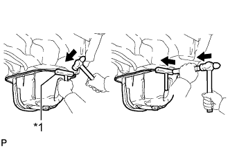
Text in Illustration *1 Oil Pan Seal Cutter Insert the blade of an oil pan seal cutter between the oil pans. Cut through the applied sealer and remove the No. 2 oil pan.
Note
Be careful not to damage the contact surfaces of the oil pans.
-
-
REMOVE OIL STRAINER SUB-ASSEMBLY
-
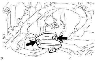
Remove the 2 nuts, oil strainer and gasket.
-
-
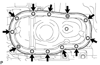
REMOVE OIL PAN SUB-ASSEMBLY
-
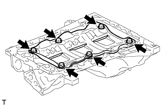
Remove the 17 bolts and 2 nuts.
Tech Tips
Make sure the removed parts are returned to the same places they were removed from.
-
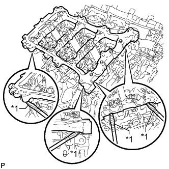
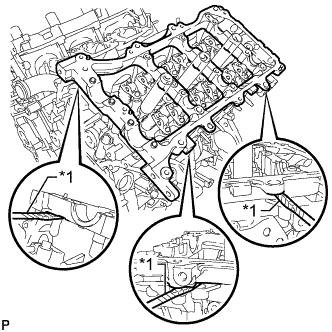
Text in Illustration *1 LH Side *2 RH Side *a Pry Using a screwdriver, remove the oil pan by prying between the oil pan and cylinder block as shown in the illustration.
Tech Tips
Tape the screwdriver tip before use.
Note
Be careful not to damage the contact surfaces of the cylinder block and oil pan.
-
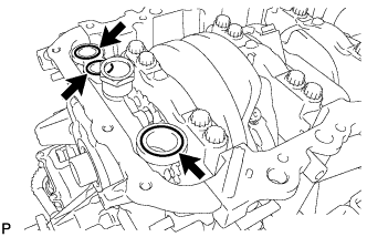
Remove the 3 O-rings from the timing chain cover.
-
-
REMOVE NO. 1 OIL PAN BAFFLE PLATE
-
Remove the 6 bolts and No. 1 oil pan baffle plate.
-
-
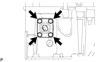
REMOVE ENGINE REAR OIL SEAL RETAINER
-
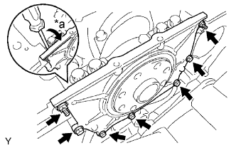
Text in Illustration *a Pry Remove the 5 bolts and 2 nuts.
-
Using a screwdriver, remove the oil seal retainer by prying between the oil seal retainer and crankshaft bearing cap.
Tech Tips
Tape the screwdriver tip before use.
-
-
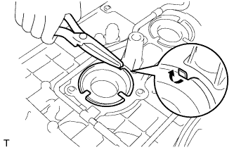
REMOVE REAR CRANKSHAFT OIL SEAL
-
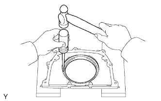
Using a screwdriver and hammer, tap out the oil seal.
Note
Be careful not to damage the rear oil seal retainer.
-
-
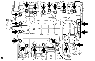
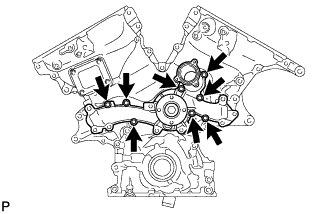
REMOVE TIMING CHAIN COVER SUB-ASSEMBLY
-
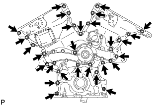
Remove the 26 bolts and the 2 nuts.
-
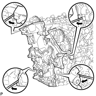
Remove the timing chain cover by prying between the timing chain cover and cylinder head or cylinder block with a screwdriver.
Tech Tips
Tape the screwdriver tip before use.
Note
Be careful not to damage the contact surfaces of the timing chain cover, cylinder block and cylinder head.
-
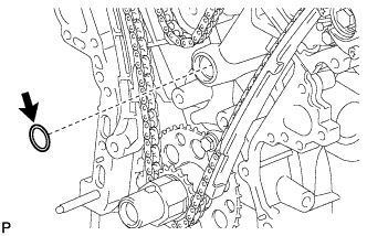
Remove the oil pump gasket from the cylinder block.
-
-
REMOVE WATER PUMP ASSEMBLY
-
Remove the 8 bolts, water pump and gasket.
-
-
REMOVE FRONT CRANKSHAFT OIL SEAL
-
Using a screwdriver and wooden block, pry out the oil seal.
Tech Tips
Tape the screwdriver tip before use.
Note
Do not damage the surface of the oil seal press fit hole.
-
-
SET NO. 1 CYLINDER TO TDC/COMPRESSION
-
Temporarily install the pulley set bolt.
-
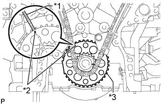
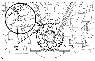
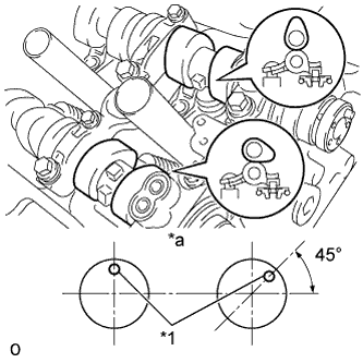
Text in Illustration *1 Center Line *2 Timing Mark *3 Sensor Plate Turn the crankshaft clockwise to align the timing mark on the crank angle sensor plate with the RH block bore center line (TDC/compression).
-
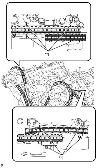
Text in Illustration *1 Timing Mark Check that the timing marks of the camshaft timing gears are aligned with the timing marks of the bearing caps as shown in the illustration.
If not, turn the crankshaft clockwise 1 revolution (360°) and align the timing marks as above.
-
-
REMOVE NO. 1 CHAIN TENSIONER ASSEMBLY
-
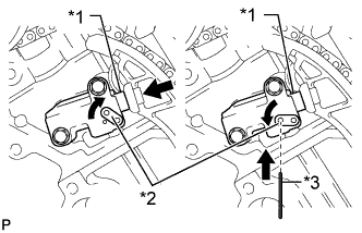
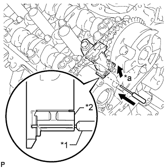
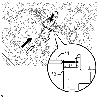
Text in Illustration *1 Plunger *2 Stopper Plate *3 Pin Move the stopper plate upward to release the lock, and push the plunger deep into the tensioner.
-
Move the stopper plate downward to set the lock, and insert a pin of φ1.27 mm (0.0500 in.) into the stopper plate hole.
-
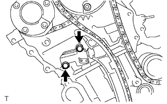
Remove the 2 bolts and No. 1 chain tensioner assembly.
-
-
REMOVE CHAIN TENSIONER SLIPPER
-
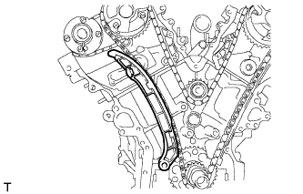
Remove the chain tensioner slipper.
-
-
REMOVE NO. 1 CHAIN SUB-ASSEMBLY
-
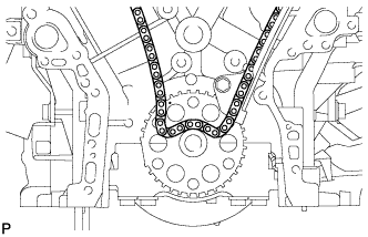
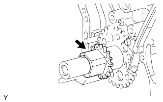
Text in Illustration *1 Center Line *2 Timing Mark *3 Sensor Plate Turn the crankshaft counterclockwise 10° to loosen the chain of the crankshaft timing sprocket.
-
Remove the pulley set bolt.
-
Remove the chain sub-assembly from the crankshaft timing sprocket and place it on the crankshaft.
-
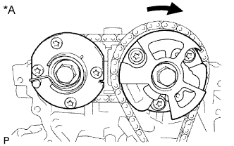
Turn the camshaft timing gear assembly on bank 1 clockwise approximately 60° so that it is as shown in the illustration. Be sure to loosen the chain sub-assembly between the banks.
-
Remove the chain sub-assembly.
Text in Illustration *A for Bank 1
-
-
REMOVE NO. 1 IDLE GEAR SHAFT
-
Using a 10 mm hexagon wrench, remove the No. 2 idle gear shaft, No. 1 idle gear and No. 1 idle gear shaft.
-
-
REMOVE NO. 1 CHAIN VIBRATION DAMPER
-
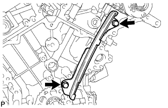
Remove the 2 bolts and No. 1 chain vibration damper.
-
-
REMOVE NO. 2 CHAIN VIBRATION DAMPER
-
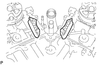
Remove the 2 No. 2 chain vibration dampers.
-
-
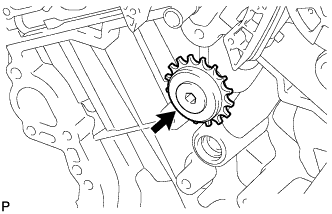
REMOVE CRANKSHAFT TIMING SPROCKET
-
Remove the crankshaft timing sprocket.
-
-
REMOVE CAMSHAFT TIMING GEARS AND NO. 2 CHAIN (for Bank 1)
-
Text in Illustration *1 Pin *2 Plunger *a Push While raising the No. 2 chain tensioner assembly, insert a pin with a diameter of 1.0 mm (0.0394 in.) into the hole to hold the No. 2 chain tensioner assembly.
-
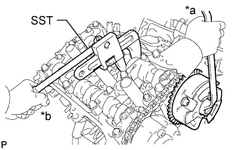
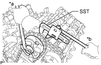
Text in Illustration *a Turn *b Hold Using SST to hold the hexagonal portion of each camshaft, loosen the bolts of the camshaft timing gear assembly and camshaft timing exhaust gear assembly.
- SST
- 09922-10010
Note
Do not loosen the other 4 bolts. If any of the 4 bolts is loosened, replace the camshaft timing gear assembly and/or camshaft timing exhaust gear assembly with a new one.
-
Remove the 2 bolts and camshaft timing gear assembly together with the No. 2 chain.
-
-
REMOVE NO. 2 CHAIN TENSIONER ASSEMBLY
-
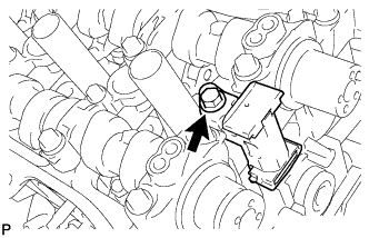
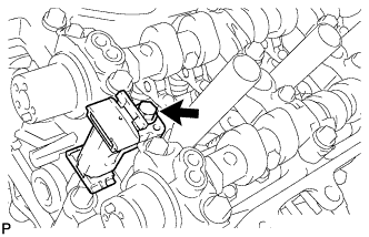
Remove the bolt and No. 2 chain tensioner assembly.
-
-
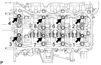
REMOVE CAMSHAFT BEARING CAP (for Bank 1)
-
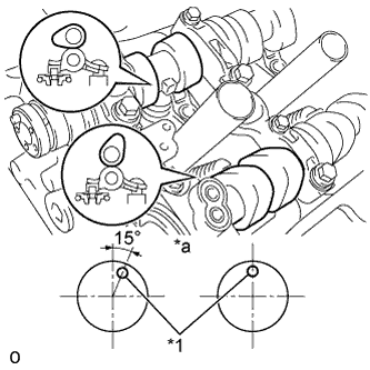
Text in Illustration *1 Knock Pin *a Front View Check that the camshafts are positioned as shown in the illustration.
-
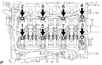
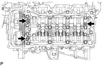
Uniformly loosen and remove the 8 bearing cap bolts in several steps in the sequence shown in the illustration.
-
Uniformly loosen and remove the 12 bearing cap bolts in several steps in the sequence shown in the illustration.
Note
Uniformly loosen the bolts while keeping the camshaft level.
-
Remove the 5 camshaft bearing caps.
-
Remove the camshaft and No. 2 camshaft.
-
-
REMOVE CAMSHAFT HOUSING SUB-ASSEMBLY RH
-
Text in Illustration *1 Protective Tape Remove the camshaft housing sub-assembly RH by prying between the cylinder head and camshaft housing sub-assembly RH with a screwdriver.
Tech Tips
Tape the screwdriver tip before use.
Note
Be careful not to damage the contact surfaces of the cylinder head and camshaft housing sub-assembly RH.
-
-
REMOVE CAMSHAFT TIMING GEARS AND NO. 2 CHAIN (for Bank 2)
-
Text in Illustration *1 Pin *2 Plunger *a Push While pushing down the No. 3 chain tensioner assembly, insert a pin with a diameter of 1.0 mm (0.0394 in.) into the hole to hold the No. 3 chain tensioner assembly.
-
Text in Illustration *a Turn *b Hold Using SST to hold the hexagonal portion of each camshaft, loosen the bolts of the camshaft timing gear assembly and camshaft timing exhaust gear assembly.
- SST
- 09922-10010
Note
Do not loosen the other 4 bolts. If any of the 4 bolts is loosened, replace the camshaft timing gear assembly and/or camshaft timing exhaust gear assembly with a new one.
-
Remove the 2 bolts and camshaft timing gear together with the No. 2 chain.
-
-
REMOVE NO. 3 CHAIN TENSIONER ASSEMBLY
-
Remove the bolt and No. 3 chain tensioner assembly.
-
-
REMOVE CAMSHAFT BEARING CAP (for Bank 2)
-
Text in Illustration *1 Knock Pin *a Front View Check that the camshafts are positioned as shown in the illustration.
-
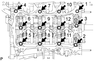
Uniformly loosen and remove the 8 bearing cap bolts in several steps in the sequence shown in the illustration.
-
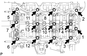
Uniformly loosen and remove the 13 bearing cap bolts in several steps in the sequence shown in the illustration.
Note
Uniformly loosen the bolts while keeping the camshaft level.
-
Remove the 5 camshaft bearing caps.
-
Remove the No. 3 camshaft and No. 4 camshaft.
-
-
REMOVE CAMSHAFT HOUSING SUB-ASSEMBLY LH
-
Text in Illustration *1 Protective Tape Remove the camshaft housing sub-assembly LH by prying between the cylinder head and camshaft housing sub-assembly LH with a screwdriver.
Tech Tips
Tape the screwdriver tip before use.
Note
Be careful not to damage the contact surfaces of the cylinder head and camshaft housing sub-assembly LH.
-
-
REMOVE NO. 1 VALVE ROCKER ARM SUB-ASSEMBLY
-
Remove the 24 valve rocker arms from the cylinder head.
Tech Tips
Arrange the removed parts in the correct order.
-
-
REMOVE VALVE LASH ADJUSTER ASSEMBLY
-
Remove the 24 valve lash adjusters from the cylinder head.
Tech Tips
Arrange the removed parts in the correct order.
-
-
REMOVE VALVE STEM CAP
-
Remove the 24 valve stem caps from the cylinder head.
Tech Tips
Arrange the removed parts in the correct order.
-
-
REMOVE CYLINDER HEAD SUB-ASSEMBLY
-
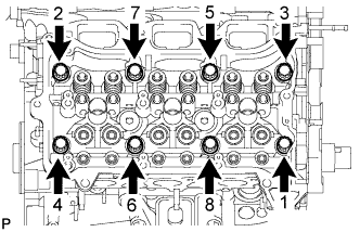
Using a 10 mm bi-hexagon wrench, uniformly loosen the 8 cylinder head bolts in the sequence shown in the illustration. Remove the 8 cylinder head bolts and plate washers.
Note
-
Be careful not to drop washers into the cylinder head sub-assembly.
-
Cylinder head warpage or cracking could result from removing bolts in an incorrect order.
Tech Tips
Arrange the removed parts in the correct order.
-
-
Remove the cylinder head sub-assembly.
-
-
REMOVE CYLINDER HEAD LH
-
Uniformly loosen and remove the 2 cylinder head set bolts in several steps in the sequence shown in the illustration.
-
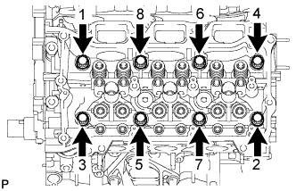
Using a 10 mm bi-hexagon wrench, uniformly loosen the 8 bolts in the sequence shown in the illustration. Remove the 8 cylinder head bolts and plate washers.
Note
-
Be careful not to drop washers into the cylinder head sub-assembly.
-
Cylinder head warpage or cracking could result from removing bolts in an incorrect order.
Tech Tips
Be sure to keep the removed parts for each installation position separate.
-
-
Remove the cylinder head LH.
-
-
REMOVE CYLINDER HEAD GASKET
-
REMOVE NO. 2 CYLINDER HEAD GASKET
-
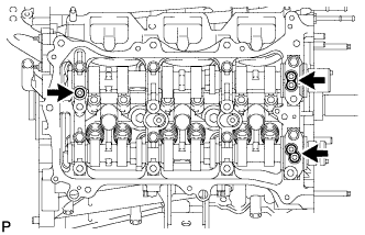
REMOVE NO. 1 WATER OUTLET PIPE
-
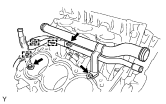
Detach the 3 wire harness clamps.
-
Remove the 2 nuts, bolt and water outlet pipe.
-
-
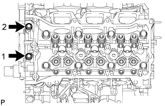
REMOVE KNOCK SENSOR
-
Disconnect the 2 sensor connectors.
-
Remove the 2 bolts and 2 sensors.
-
-
REMOVE CYLINDER BLOCK WATER JACKET SPACER
-
Remove the 2 water jacket spacers from the cylinder head.
Note
Be sure to remove the water jacket spacers. If not, they may fall and become damaged when the cylinder block is inverted.
-
-
REMOVE TAPER SCREW PLUG
Note
It is not necessary to remove a taper screw plug unless it is being replaced.
-
REMOVE STRAIGHT PIN
Note
It is not necessary to remove a straight pin unless it is being replaced.
-
REMOVE RING PIN
Note
It is not necessary to remove a ring pin unless it is being replaced.
-
REMOVE STUD BOLT
Note
It is not necessary to remove a stud bolt unless it is being replaced.