CAMSHAFT INSTALLATION

-
INSPECT CAMSHAFT TIMING GEAR ASSEMBLY
-
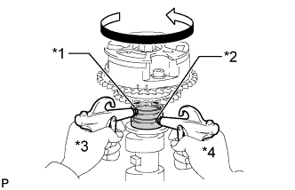
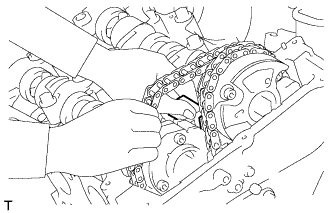
Fix the camshaft in place.
Note
Be careful not to damage the camshaft.
-
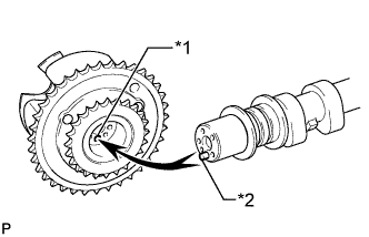
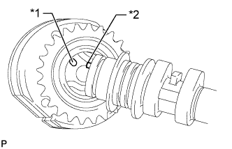
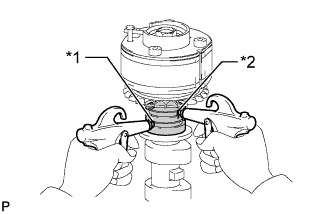
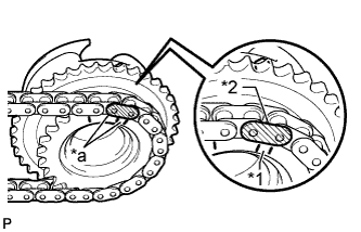
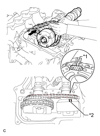
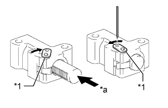
Text in Illustration *1 Pin Hole *2 Straight Pin Put the camshaft timing gear assembly and camshaft together by aligning the pin hole and straight pin.
-
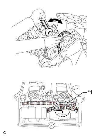
Lightly press and turn the camshaft timing gear assembly against the camshaft, and press harder after the pin enters the hole.
Note
Be sure not to turn the camshaft timing gear assembly in the retard direction.
-
Check that there is no clearance between the camshaft timing gear assembly flange and camshaft.
-
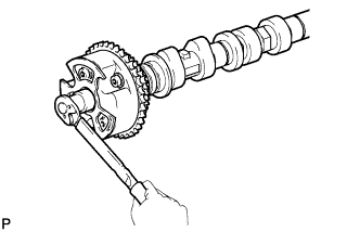
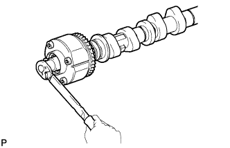
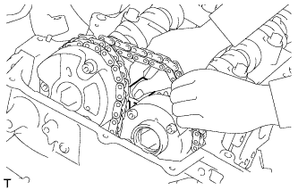
Tighten the flange bolt while holding the camshaft.
- Torque:
- 100 N*m { 1020 kgf*cm, 74 ft.*lbf }
-
Check the lock of the camshaft timing gear assembly.
-
Fix the camshaft in place and confirm that the camshaft timing gear assembly is locked.
Note
Be careful not to damage the camshaft.
-
-
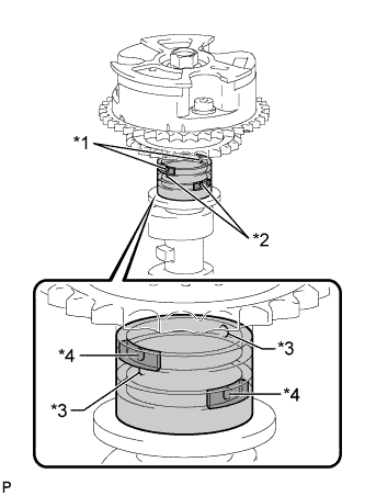
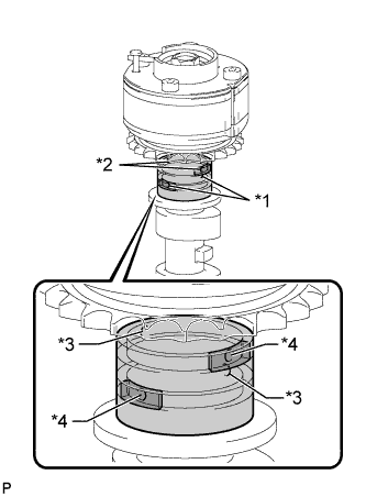
Text in Illustration *1 Advance Side Path *2 Retard Side Path *3 Open *4 Close 
Rubber 
Vinyl Tape Release the lock pin.
-
Cover the 4 oil paths of the cam journal with vinyl tape as shown in the illustration.
Tech Tips
The 2 advance side paths are located in the camshaft groove. Plug one of the paths with a rubber piece.
-
Break through the tape on the advance side path and the retard side path on the opposite side of the hole of the advance side path, as shown in the illustration.
-
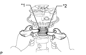
Text in Illustration *1 Advance Side Path *2 Retard Side Path Apply air at approximately 200 kPa (2.0 kgf/cm2, 28 psi) to the 2 open paths.
CAUTION:
Cover the paths with a piece of cloth when applying pressure to prevent oil from spraying.
-
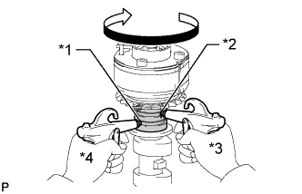
Text in Illustration *1 Advance Side Path *2 Retard Side Path *3 Hold Pressure *4 Decompress Check that the camshaft timing gear assembly rotates in the advance direction when reducing the air pressure applied to the retard side path.
Tech Tips
This operation releases the lock pin at the most retarded position.
-
When the camshaft timing gear assembly reaches the most advanced position, release the air pressure first from the retard side path and next from the advance side path.
Note
Do not release the air pressure from the advance side path first. The gear may abruptly shift in the retard direction and break the lock pin.
-
-
Check for smooth rotation.
-
Turn the camshaft timing gear assembly within its movable range (21°) 2 or 3 times, but do not turn it to the most retarded position. Make sure that the gear turns smoothly.
Note
Do not use air pressure to perform the smooth operation check.
-
-
Check the lock in the most retarded position.
-
Confirm that the camshaft timing gear assembly locks at the most retarded position.
-
-
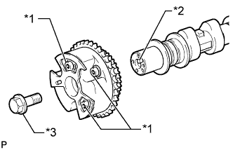
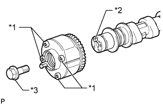
Text in Illustration *1 Do not remove *2 Straight Pin *3 Flange Bolt Remove the flange bolt and camshaft timing gear assembly.
Note
-
Do not remove the other 3 bolts.
-
If planning to reuse the camshaft timing gear, be sure to release the straight pin lock before installing the camshaft timing gear.
-
-
-
INSPECT CAMSHAFT TIMING EXHAUST GEAR ASSEMBLY
-
Fix the camshaft in place.
Note
Be careful not to damage the camshaft.
-
Text in Illustration *1 Pin Hole *2 Straight Pin Put the camshaft timing exhaust gear assembly and camshaft together by aligning the pin hole and straight pin.
-
Lightly press and turn the camshaft timing gear assembly against the camshaft, and press harder after the pin enters the hole.
Note
Be sure not to turn the camshaft timing exhaust gear in the advanced direction.
-
Check that there is no clearance between the gear flange and camshaft.
-
Tighten the flange bolt while holding the camshaft.
- Torque:
- 100 N*m { 1020 kgf*cm, 74 ft.*lbf }
-
Check the camshaft timing exhaust gear lock.
-
Make sure that the camshaft timing exhaust gear assembly locks.
-
-
Text in Illustration *1 Advance Side Path *2 Retard Side Path *3 Open *4 Close Rubber Vinyl Tape Release the lock pin.
-
Cover the 4 oil paths of the cam journal with vinyl tape as shown in the illustration.
Tech Tips
The 2 advance side paths are located in the camshaft groove. Plug one of the paths with a rubber piece.
-
Break through the tape on the advance side path and the retard side path on the opposite side of the hole of the advance side path, as shown in the illustration.
-
Text in Illustration *1 Advance Side Path *2 Retard Side Path Apply air at approximately 200 kPa (2.0 kgf/cm2, 28 psi) to the 2 open paths (the advance side path and retard side path).
CAUTION:
Cover the paths with a piece of cloth when applying pressure to prevent oil from spraying.
-
Text in Illustration *1 Advance Side Path *2 Retard Side Path *3 Hold Pressure *4 Decompress Make sure that the camshaft timing exhaust gear assembly rotates in the retard direction when reducing the air pressure applied to the advance side path.
Tech Tips
The lock pin is released and the camshaft timing exhaust gear assembly turns in the retard direction.
-
When the camshaft timing exhaust gear assembly moves to the most retarded position, release the air pressure first from the advance side path, and then release the air pressure from the retard side path.
Note
Be sure to release the air pressure from the advance side path first. If the air pressure of the retard side path is released first, the camshaft timing exhaust gear assembly may abruptly shift in the advance direction and break the lock pin or other parts.
-
-
Check for smooth rotation.
-
Turn the camshaft timing exhaust gear assembly within its movable range (18.5°) 2 or 3 times, but do not turn it to the most advanced position. Make sure that the gear assembly turns smoothly.
Note
When the air pressure is released from the advance side path and then from the retard side path, the gear assembly automatically returns to the most advanced position due to the advance assist spring operation and locks. Gradually release the air pressure from the retard side path before performing the smooth rotation check.
-
-
Check the lock at the most advanced position.
-
Make sure that the camshaft timing exhaust gear assembly locks at the most advanced position.
-
-
Text in Illustration *1 Do not remove *2 Straight Pin *3 Flange Bolt Remove the flange bolt and camshaft timing exhaust gear assembly.
Note
-
Be sure not to remove the other 4 bolts.
-
If planning to reuse the gear, be sure to release the straight pin lock before installing the gear.
-
-
-
INSTALL CAMSHAFT TIMING GEAR ASSEMBLY
-
Fix the camshaft in place.
Note
Be careful not to damage the camshaft.
-
Text in Illustration *1 Pin Hole *2 Straight Pin Put the camshaft timing gear assembly and camshaft together by aligning the pin hole and straight pin.
-
Lightly press and turn the camshaft timing gear assembly against the camshaft, and press harder after the pin enters the hole.
Note
Be sure not to turn the camshaft timing gear assembly in the retard direction.
-
Check that there is no clearance between the camshaft timing gear assembly flange and camshaft.
-
Install the flange bolt while holding the camshaft.
- Torque:
- 100 N*m { 1020 kgf*cm, 74 ft.*lbf }
-
Check the lock of the camshaft timing gear assembly.
-
Fix the camshaft in place and confirm that the camshaft timing gear assembly is locked.
Note
Be careful not to damage the camshaft.
-
-
-
INSTALL CAMSHAFT TIMING EXHAUST GEAR ASSEMBLY
-
Fix the camshaft in place.
Note
Be careful not to damage the camshaft.
-
Text in Illustration *1 Pin Hole *2 Straight Pin Put the camshaft timing exhaust gear assembly and camshaft together by aligning the pin hole and straight pin.
-
Lightly press and turn the camshaft timing gear assembly against the camshaft, and press harder after the pin enters the hole.
Note
Be sure not to turn the camshaft timing exhaust gear in the advanced direction.
-
Check that there is no clearance between the gear flange and camshaft.
-
Install the flange bolt while holding the camshaft.
- Torque:
- 100 N*m { 1020 kgf*cm, 74 ft.*lbf }
-
Check the camshaft timing exhaust gear lock.
-
Make sure that the camshaft timing exhaust gear assembly locks.
-
-
-
INSTALL NO. 3 CAMSHAFT
-
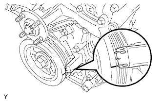
Check that the notch is aligned with the "0" timing mark of the timing chain cover.
-
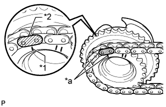
Text in Illustration *1 Timing Mark *2 Mark Plate (yellow) *a Align Align the mark plate (yellow) with the timing mark of the camshaft timing gear as shown in the illustration and install the No. 2 chain to the camshaft timing gear.
-
Clean the camshaft housing LH and camshaft journals and apply engine oil to them.
-
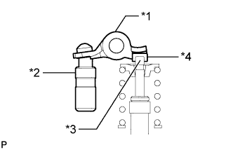
Text in Illustration *1 Valve Rocker Arm *2 Lash Adjuster *3 Valve Stem *4 Valve Stem Cap Make sure that the No. 1 valve rocker arm sub-assembly is installed as shown in the illustration.
-
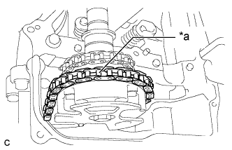
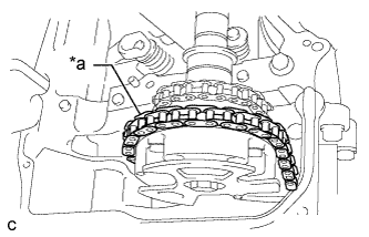
Text in Illustration *a Place on camshaft timing gear Install the chain to the No. 3 camshaft, and then install the camshaft to the camshaft housing LH.
Tech Tips
-
Place the chain on the camshaft timing gear but do not engage the teeth of the sprocket and the chain.
-
Install the camshaft so that the timing mark is facing upward.
-
-
-
INSTALL NO. 4 CAMSHAFT
-
Clean the camshaft housing LH and camshaft journals and apply engine oil to them.
-
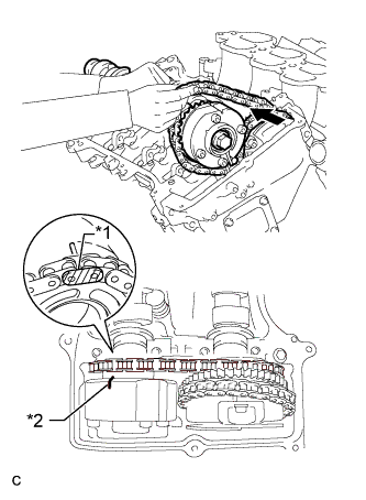
Text in Illustration *1 Mark Plate (yellow) *2 Timing Mark Pass the No. 4 camshaft through the No. 2 chain from the front of the vehicle, align the mark plate (yellow) with the timing mark and install the No. 2 chain to the camshaft timing exhaust gear.
Tech Tips
The mark plate is yellow.
-
While lifting up the No. 4 camshaft, pass the No. 3 chain tensioner assembly through the No. 2 chain and set it in place.
-
Install the No. 4 camshaft to the camshaft housing LH, and then install the No. 3 chain tensioner assembly with the bolt.
- Torque:
- 21 N*m { 214 kgf*cm, 15 ft.*lbf }
-
-
INSTALL CAMSHAFT BEARING CAP (for Bank 2)
-
Clean the camshaft bearing caps and apply engine oil to them.
-
Text in Illustration *1 Valve Rocker Arm *2 Lash Adjuster *3 Valve Stem *4 Valve Stem Cap Make sure that the No. 1 valve rocker arm sub-assembly is installed as shown in the illustration.
-
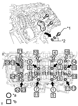
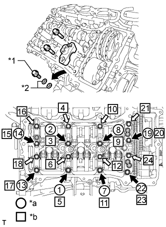
Text in Illustration *1 Bolt *2 Washer *a Installation of Bolts and Washers for Temporary Installation of camshaft housing *b Part Installation 
Bolt A 
Bolt B Check the marks and numbers on the camshaft bearing caps, and then remove the replacement bolts and washers in the order shown in the illustration. Immediately after removing the bolts and washers for temporary installation of the camshaft housing in the location for a bearing cap, install the bearing cap with the bolts in the order shown in the illustration.
- Torque:
- for bolt A
- 28 N*m { 286 kgf*cm, 21 ft.*lbf }
- for bolt B
- 16 N*m { 163 kgf*cm, 12 ft.*lbf }
Note
-
Be sure to follow the numerical order when performing this procedure.
-
Do not drop bolts and washers for temporary installation of the camshaft housing into the cylinder head.
-
Check the torque of each bolt again.
-
-
CONNECT CHAIN SUB-ASSEMBLY (for Bank 2)
-
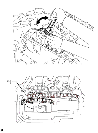
Text in Illustration *1 Paint Mark Align the paint marks on the camshaft timing gear and No. 1 chain and install the No. 1 chain to the camshaft timing gear.
Tech Tips
If the paint marks are not aligned, align them by turning the camshaft slightly.
-
-
INSTALL CAMSHAFT
-
Turn the crankshaft clockwise until it is in the position shown in the illustration so that the chain can be installed easily.
Tech Tips
When turning the crankshaft, engine oil may spray out of the oil holes.
-
Text in Illustration *1 Timing Mark *2 Mark Plate (yellow) *a Align Align the mark plate (yellow) with the timing mark of the camshaft timing gear as shown in the illustration and install the No. 2 chain to the camshaft timing gear.
-
Clean the camshaft housing RH and camshaft journals and apply engine oil to them.
-
Text in Illustration *1 Valve Rocker Arm *2 Lash Adjuster *3 Valve Stem *4 Valve Stem Cap Make sure that the No. 1 valve rocker arm sub-assembly is installed as shown in the illustration.
-
Text in Illustration *a Place on camshaft timing gear Install the chain to the camshaft, and then install the camshaft to the camshaft housing RH.
Tech Tips
-
Place the chain on the camshaft timing gear but do not engage the teeth of the sprocket and the chain.
-
Install the camshaft so that the timing mark is facing upward.
-
-
-
INSTALL NO. 2 CAMSHAFT
-
Clean the camshaft housing RH and camshaft journals and apply engine oil to them.
-
Text in Illustration *1 Mark Plate (yellow) *2 Timing Mark Pass the No. 2 camshaft through the No. 2 chain from the front of the vehicle, align the mark plate (yellow) with the timing mark and install the No. 2 chain to the camshaft timing exhaust gear.
Tech Tips
The mark plate is yellow.
-
While lifting up the No. 2 camshaft, pass the No. 2 chain tensioner assembly through the No. 2 chain and set it in place.
-
Install the No. 2 camshaft to the camshaft housing RH, and then install the No. 2 chain tensioner assembly with the bolt.
- Torque:
- 21 N*m { 214 kgf*cm, 15 ft.*lbf }
-
-
INSTALL CAMSHAFT BEARING CAP (for Bank 1)
-
Clean the camshaft bearing caps and apply engine oil to them.
-
Text in Illustration *1 Valve Rocker Arm *2 Lash Adjuster *3 Valve Stem *4 Valve Stem Cap Make sure that the No. 1 valve rocker arm sub-assembly is installed as shown in the illustration.
-
Text in Illustration *1 Bolt *2 Washer *a Installation of Bolts and Washers for Temporary Installation of camshaft housing *b Part Installation Bolt A Bolt B Check the marks and numbers on the camshaft bearing caps, and then remove the replacement bolts and washers in the order shown in the illustration. Immediately after removing the bolts and washers for temporary installation of the camshaft housing in the location for a bearing cap, install the bearing cap with the bolts in the order shown in the illustration.
- Torque:
- for bolt A
- 28 N*m { 286 kgf*cm, 21 ft.*lbf }
- for bolt B
- 16 N*m { 163 kgf*cm, 12 ft.*lbf }
Note
-
Be sure to follow the numerical order when performing this procedure.
-
Do not drop bolts and washers for temporary installation of the camshaft housing into the cylinder head.
-
Check the torque of each bolt again.
-
-
CONNECT CHAIN SUB-ASSEMBLY (for Bank 1)
-
Text in Illustration *1 Paint Mark Align the paint marks on the camshaft timing gear and No. 1 chain and install the No. 1 chain to the camshaft timing gear.
Tech Tips
If the paint marks are not aligned, align them by turning the camshaft slightly.
-
-
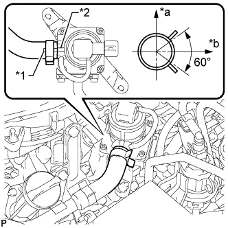
INSTALL NO. 1 CHAIN TENSIONER ASSEMBLY
-
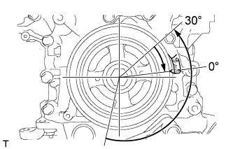
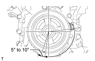
Turn the crankshaft counterclockwise 30° past the "0" timing mark, and then turn it clockwise to align the notch with the "0" timing mark.
-
Turn the crankshaft slightly to eliminate the slack in the chain.
Tech Tips
Make sure there is some slack in the chain around the area where the chain tensioner is installed.
-
Text in Illustration *1 Stopper Plate *a Push While turning the stopper plate of the tensioner clockwise, push in the plunger of the tensioner as shown in the illustration.
-
While turning the stopper plate of the tensioner counterclockwise, insert a pin of φ1.27 mm (0.0500 in.) into the holes in the stopper plate and tensioner to fix the stopper plate in place.
-
Install the chain tensioner with the 2 bolts.
- Torque:
- 10 N*m { 102 kgf*cm, 7 ft.*lbf }
-
Remove the pin from the No. 1 chain tensioner.
-
-
INSPECT VALVE TIMING
-
Check the camshaft timing marks.
Note
-
Check each timing mark from a viewpoint directly in line with the center of the camshaft and the timing mark on each camshaft timing gear.
-
If the timing marks are checked from any other viewpoint, the valve timing may appear misaligned.
-
-
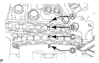
Check that each camshaft timing mark is positioned as shown in the illustration.
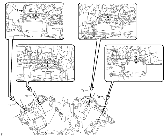
Text in Illustration *1 Timing Mark - - *a Viewpoint - - Tech Tips
for Intake Camshaft:
Be sure to check mark A at the point when marks B, C and D are positioned in line. If the marks are checked from any other viewpoint, they cannot be checked correctly.
-
If the valve timing is misaligned, reinstall the timing chain.
-
Turn the crankshaft 2 revolutions, set the No. 1 cylinder to TDC/compression and check the timing marks again.
-
-
INSTALL TIMING CHAIN COVER PLATE
-
Install a new gasket and the timing chain cover plate with the 4 bolts.
- Torque:
- 9.0 N*m { 92 kgf*cm, 80 in.*lbf }
-
-
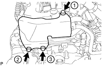
POUR ENGINE OIL
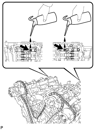
Tech Tips
Before installing the cylinder head cover, pour engine oil into the locations shown in the illustration.
-
INSTALL CYLINDER HEAD COVER SUB-ASSEMBLY
-
Remove any old packing (FIPG material) and be careful not to drop any oil on the contact surfaces of the cylinder head, timing chain cover and cylinder head cover.
-
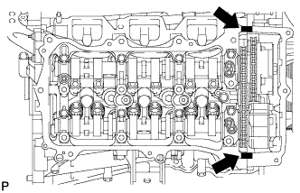
Apply seal packing as shown in the illustration.
Seal packing Toyota Genuine Seal Packing Black, Three Bond 1207B or equivalent Standard seal diameter 2.0 to 3.0 mm (0.0787 to 0.118 in.) Text in Illustration Seal Packing Note
-
Remove any oil from the contact surface.
-
Install the cylinder head cover within 3 minutes and tighten the bolts within 15 minutes after applying seal packing.
-
-
Install 3 new gaskets.
-
Install a new gasket to the cylinder head cover.
-
Install the seal washers to the bolts.
-
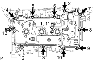
Temporarily install the cylinder head cover with the 12 bolts. Tighten the bolts uniformly in several steps.
- Torque:
- for bolt A and D
- 10 N*m { 102 kgf*cm, 7 ft.*lbf }
- for bolt B and C
- 21 N*m { 214 kgf*cm, 15 ft.*lbf }
Standard Bolt Item Length A 25 mm (0.984 in.) B 35 mm (1.38 in.) C 65 mm (2.56 in.) D 60 mm (2.36 in.) Text in Illustration Bolt A Bolt B 
Bolt C 
Bolt D Note
Do not start the engine for at least 2 hours after installation.
-
-
INSTALL CYLINDER HEAD COVER SUB-ASSEMBLY LH
-
Remove any old packing (FIPG material) and be careful not to drop any oil on the contact surfaces of the cylinder head, timing chain cover and cylinder head cover.
-
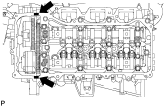
Apply seal packing as shown in the illustration.
Seal packing Toyota Genuine Seal Packing Black, Three Bond 1207B or equivalent Standard seal diameter 2.0 to 3.0 mm (0.0787 to 0.118 in.) Text in Illustration Seal Packing Note
-
Remove any oil from the contact surface.
-
Install the cylinder head cover within 3 minutes and tighten the bolts within 15 minutes after applying seal packing.
-
-
Install 3 new gaskets.
-
Install a new gasket to the cylinder head cover.
-
Install the seal washers to the bolts.
-
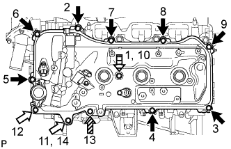
Temporarily install the cylinder head cover with the 12 bolts. Tighten the bolts uniformly in several steps.
- Torque:
- for bolt A and D
- 10 N*m { 102 kgf*cm, 7 ft.*lbf }
- for bolt B and C
- 21 N*m { 214 kgf*cm, 15 ft.*lbf }
Standard Bolt Item Length A 25 mm (0.984 in.) B 35 mm (1.38 in.) C 70 mm (2.76 in.) D 60 mm (2.36 in.) Text in Illustration Bolt A Bolt B Bolt C Bolt D Note
Do not start the engine for at least 2 hours after installation.
-
-
CONNECT FUEL PIPE SUB-ASSEMBLY
-
Connect the fuel pipe with the 2 bolts.
- Torque:
- 9.0 N*m { 92 kgf*cm, 80 in.*lbf }
-
-
INSTALL REAR CYLINDER HEAD COVER
-
Temporarily install the cover with the 3 bolts.
-
Tighten the 3 bolts in the sequence shown in the illustration.
- Torque:
- 9.0 N*m { 92 kgf*cm, 80 in.*lbf }
-
-
INSTALL NO. 2 OIL PIPE
-
Make sure that there is no foreign matter on the mesh of the oil control valve filter RH.
Note
Do not touch the mesh when installing the oil control valve filter.
-
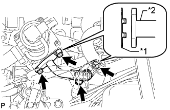
Install a new gasket and temporarily install the oil pipe (on the cylinder head side) with the oil check valve bolt.
-
Install the oil control valve filter RH to the oil pipe union. Install new gaskets and temporarily install the oil pipe (on the head cover side).
-
Tighten the oil pipe union (on the cylinder head side).
- Torque:
- 65 N*m { 663 kgf*cm, 48 ft.*lbf }
Note
If the link that connects the gaskets is broken, remove the connecting link by using side cutters or a similar tool.
-
Tighten the oil pipe union (on the head cover side).
- Torque:
- 65 N*m { 663 kgf*cm, 48 ft.*lbf }
-
-
INSTALL NO. 1 OIL PIPE
-
Make sure that there is no foreign matter on the mesh of the oil control valve filter LH.
Note
Do not touch the mesh when installing the oil control valve filter.
-
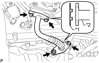
Install a new gasket and temporarily install the oil pipe (on the cylinder head side) with the oil check valve bolt.
-
Install the oil control valve filter LH to the oil pipe union. Install new gaskets and temporarily install the oil pipe (on the head cover side).
-
Tighten the oil pipe union (on the cylinder head side).
- Torque:
- 65 N*m { 663 kgf*cm, 48 ft.*lbf }
Note
If the link that connects the gaskets is broken, remove the connecting link by using side cutters or a similar tool.
-
Tighten the oil pipe union (on the head cover side).
- Torque:
- 65 N*m { 663 kgf*cm, 48 ft.*lbf }
-
-
INSTALL WATER BY-PASS PIPE SUB-ASSEMBLY (w/ Oil Cooler)
-
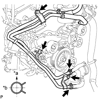
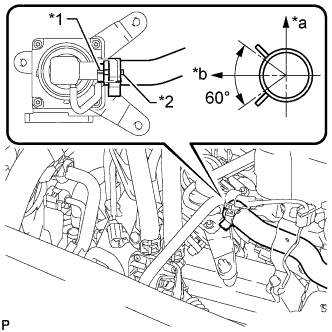
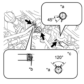
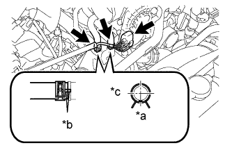
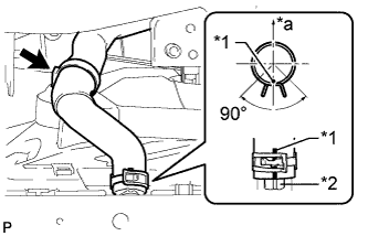
Text in Illustration *a Upward *b Rearward Install the water by-pass pipe with the 3 bolts.
- Torque:
- 10 N*m { 102 kgf*cm, 7 ft.*lbf }
-
Connect the 2 hoses.
Tech Tips
The direction of the hose clamp is indicated in the illustration.
-
-
INSTALL ENGINE OIL LEVEL DIPSTICK GUIDE
-
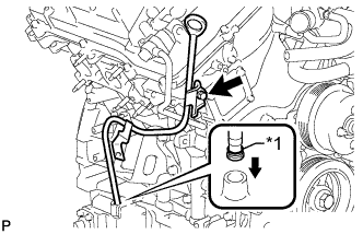
Text in Illustration *1 New O-Ring Install a new O-ring to the dipstick guide.
-
Apply a light coat of engine oil to the O-ring.
-
Push the dipstick guide end into the guide hole.
-
Install the dipstick guide with the bolt.
- Torque:
- 10 N*m { 102 kgf*cm, 7 ft.*lbf }
-
Install the dipstick.
-
-
INSTALL GENERATOR ASSEMBLY
-
Install the generator bracket to the generator with the bolt.
- Torque:
- 20 N*m { 204 kgf*cm, 15 ft.*lbf }
-
Install the generator with the 2 bolts.
- Torque:
- 43 N*m { 438 kgf*cm, 32 ft.*lbf }
-
Install the generator bracket with the bolt.
- Torque:
- 20 N*m { 204 kgf*cm, 15 ft.*lbf }
-
Connect the wire harness clamp.
-
Install the wire harness with the 2 bolts.
- Torque:
- 8.0 N*m { 82 kgf*cm, 71 in.*lbf }
-
Connect the generator connector to the generator.
-
Connect the generator wire with the nut.
- Torque:
- 9.8 N*m { 100 kgf*cm, 87 in.*lbf }
-
Close the terminal cap.
-
-
INSTALL NO. 2 EXHAUST MANIFOLD HEAT INSULATOR
-
Install the heat insulator with the 3 bolts.
- Torque:
- 13 N*m { 133 kgf*cm, 10 ft.*lbf }
-
-
INSTALL WIRING HARNESS CLAMP BRACKET
-
Install the wiring harness clamp bracket with the bolt.
- Torque:
- 8.0 N*m { 82 kgf*cm, 71 in.*lbf }
-
Attach the clamp.
-
-
INSTALL NO. 2 IDLER PULLEY SUB-ASSEMBLY
-
for Integrated Type:
Install the No. 2 idler pulley with the bolt.
- Torque:
- 54 N*m { 551 kgf*cm, 40 ft.*lbf }
-
for Separate Type:
Install the No. 2 idler pulley cover plate, No. 2 idler pulley and idler pulley cover plate with the bolt.
- Torque:
- 54 N*m { 551 kgf*cm, 40 ft.*lbf }
-
-
CONNECT VANE PUMP ASSEMBLY
-
Connect the vane pump with the 2 bolts.
- Torque:
- 43 N*m { 438 kgf*cm, 32 ft.*lbf }
-
Attach the 2 wire harness clamps.
-
Connect the 2 connectors.
-
-
INSTALL IGNITION COIL ASSEMBLY
-
Install the 6 ignition coils with the 6 bolts.
- Torque:
- 10 N*m { 102 kgf*cm, 7 ft.*lbf }
-
Connect the 6 ignition coil connectors.
-
-
INSTALL NO. 2 EMISSION CONTROL VALVE SET (w/ Secondary Air Injection System)
-
Install the No. 2 emission control valve set with the 3 nuts.
- Torque:
- 21 N*m { 214 kgf*cm, 15 ft.*lbf }
-
Text in Illustration *1 Paint Mark *2 Rib *a Upper *b LH Side Align the paint mark with the projection and connect the No. 1 air hose.
Tech Tips
Make sure the direction of the hose clamp is as shown in the illustration.
-
Connect the No. 2 emission control valve set connector.
-
-
INSTALL EMISSION CONTROL VALVE SET (w/ Secondary Air Injection System)
-
Install the emission control valve set with the 3 nuts.
- Torque:
- 21 N*m { 214 kgf*cm, 15 ft.*lbf }
-
Text in Illustration *1 Rib *2 Paint mark *a RH Side *b Upper Align the paint mark with the projection and connect the No. 1 air hose.
Tech Tips
Make sure the direction of the hose clamp is as shown in the illustration.
-
Connect the emission control valve set connector.
-
-
INSTALL NO. 2 AIR TUBE (w/ Secondary Air Injection System)
-
Text in Illustration *1 New Gasket *2 No. 2 Air Tube Install 2 new gaskets to the No. 2 air tube.
-
Install the No. 2 air tube with the 2 bolts and 2 nuts.
- Torque:
- 10 N*m { 102 kgf*cm, 7 ft.*lbf }
-
-
INSTALL AIR TUBE (w/ Secondary Air Injection System)
-
Text in Illustration *1 New Gasket *2 Air Tube Install 2 new gaskets to the air tube.
-
Install the air tube with the 2 bolts and 2 nuts.
- Torque:
- 10 N*m { 102 kgf*cm, 7 in.*lbf }
-
-
INSTALL INTAKE AIR SURGE TANK
-
Install a new gasket to the intake air surge tank.
-
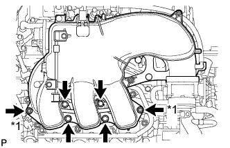
Text in Illustration *1 Nut Install the intake air surge tank with the 4 bolts and 2 nuts in the order shown in the illustration.
- Torque:
- 28 N*m { 286 kgf*cm, 21 ft.*lbf }
-
Install the No. 1 surge tank stay with the 2 bolts.
- Torque:
- 21 N*m { 214 kgf*cm, 15 ft.*lbf }
-
Attach the wire harness clamp.
-
Install the No. 2 surge tank stay with the 2 bolts.
- Torque:
- 21 N*m { 214 kgf*cm, 15 ft.*lbf }
-
Install the throttle body bracket with the 2 bolts.
- Torque:
- 21 N*m { 214 kgf*cm, 15 ft.*lbf }
-
Text in Illustration *a Front *b Matchmark *c Top Connect the No. 1 ventilation hose.
-
Connect the No. 1 vacuum switching valve connector.
-
Connect the No.1 fuel feed hose.
Tech Tips
Connect the hose so that the direction of the hose clamp is as indicated in the illustration.
-
Text in Illustration *a Front *b Matchmark *c RH Connect the throttle body connector.
-
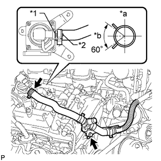
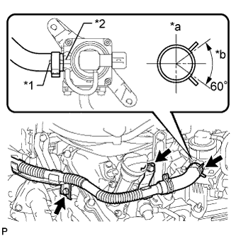
Connect the No. 4 water by-pass hose.
-
Connect the No. 5 water by-pass hose.
Tech Tips
Connect the hose so that the direction of the hose clamp is as indicated in the illustration.
-
Connect the 2 heater hose clamps.
-
-
INSTALL AIR TUBE ASSEMBLY (w/ Secondary Air Injection System)
-
Text in Illustration *1 Rib *2 Paint Mark *a RH Side *b Upper for Bank 1 Side:
Align the paint mark with the projection and connect the air tube assembly to the emission control valve set.
Tech Tips
Make sure the direction of the hose clamp is as shown in the illustration.
-
Text in Illustration *1 Paint Mark *2 Rib *a Upper *b LH Side for Bank 2 Side:
Align the paint mark with the projection and connect the air tube assembly to the No. 2 emission control valve set.
Tech Tips
Make sure the direction of the hose clamp is as shown in the illustration.
-
Install the 3 bolts.
- Torque:
- 10 N*m { 102 kgf*cm, 7 ft.*lbf }
-
-
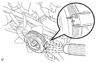
INSTALL FAN SHROUD
-
Install the fan pulley to the water pump.
-
Place the shroud together with the coupling fan between the radiator and engine.
Note
Be careful not to damage the radiator core.
-
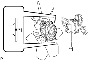
Text in Illustration *1 Paint Mark Align the paint marks on the heads of the water pump stud bolts with the paint marks of the same color on the outer edge of the fluid coupling flange and install the fluid coupling to the water pump.
-
Temporarily install the fluid coupling fan to the water pump with the 4 nuts. Tighten the nuts as much as possible by hand.
-
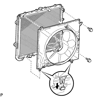
Attach the claws of the shroud to the radiator as shown in the illustration.
-
Install the shroud with the 2 bolts.
- Torque:
- 5.0 N*m { 51 kgf*cm, 44 in.*lbf }
-
Install the fan and generator V-belt Click here.
-
Tighten the 4 nuts of the fluid coupling fan.
- Torque:
- 21 N*m { 214 kgf*cm, 15 ft.*lbf }
-
-
CONNECT OIL COOLER TUBE (w/ Air Cooled Transmission Oil Cooler)
-
Connect the oil cooler tube with the 2 bolts, and attach the claw to close the flexible hose clamp.
- Torque:
- 5.5 N*m { 56 kgf*cm, 49 in.*lbf }
-
-
CONNECT OIL COOLER TUBE (w/ Warmer)
-
Connect the oil cooler tube with the 2 bolts, and attach the claw to close the flexible hose clamp.
- Torque:
- 5.5 N*m { 56 kgf*cm, 49 in.*lbf }
-
-
INSTALL RADIATOR RESERVOIR
-
Install the radiator reservoir with the 3 bolts.
- Torque:
- 5.0 N*m { 51 kgf*cm, 44 in.*lbf }
-
Connect the reservoir hose to upper side of the radiator tank upper.
-
-
INSTALL NO. 2 RADIATOR HOSE
-
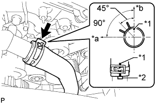
Text in Illustration *1 Paint Mark *2 Protrusion *a Upper Connect the No. 2 radiator hose so that its paint mark aligns with the radiator protrusion as shown in the illustration.
Tech Tips
-
Make sure the paint mark of the No. 1 air injection system hose is facing upward.
-
Make sure the direction of the hose clamp is as shown in the illustration.
-
-
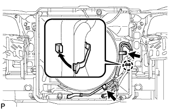
Text in Illustration *1 Paint Mark *2 Protrusion *a Front *b Upper Connect the No. 2 radiator hose so that its paint mark aligns with the water inlet housing protrusion as shown in the illustration.
Tech Tips
-
Make sure the paint mark of the No. 1 air injection system hose is facing upward.
-
Make sure the direction of the hose clamp is as shown in the illustration.
-
-
-
INSTALL NO. 1 RADIATOR HOSE
-
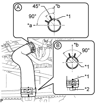
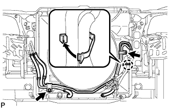
Text in Illustration *1 Paint Mark *2 Protrusion *a Front *b Upper Connect the No. 1 radiator hose to the water inlet housing shown in the illustration labeled A.
Tech Tips
-
Make sure the paint mark of the No. 1 radiator hose is facing upward.
-
Make sure the direction of the hose clamp is as shown in the illustration.
-
-
Connect the No. 1 radiator hose so that its paint mark aligns with the radiator protrusion as shown in the illustration labeled B.
Tech Tips
-
Make sure the paint mark of the No. 1 radiator hose is facing upward.
-
Make sure the direction of the hose clamp is as shown in the illustration.
-
-
-
INSTALL AIR CLEANER CASE SUB-ASSEMBLY
-
Install the air cleaner case with the 3 bolts.
- Torque:
- 12 N*m { 122 kgf*cm, 9 ft.*lbf }
-
Attach the wire harness clamp.
-
Install the air cleaner filter element.
-
-
INSTALL AIR CLEANER CAP AND HOSE
-
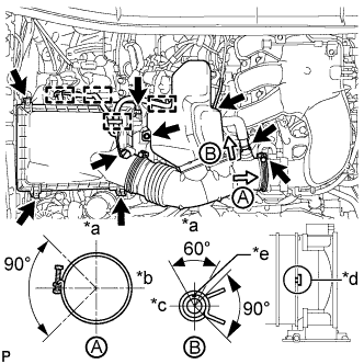
Text in Illustration *a Top *b Front *c RH *d Align cutout portion of hose with protrusion of throttle *e Paint Mark Install the air cleaner cap and hose.
-
Install the air cleaner cap and hose with the bolt and fasten the 4 hook clamps.
- Torque:
- 5.0 N*m { 51 kgf*cm, 44 in.*lbf }
-
Tighten the clamp.
- Torque:
- 5.0 N*m { 51 kgf*cm, 44 in.*lbf }
-
Attach the 4 clamps and connect the ventilation hose, vacuum hose and mass air flow meter connector.
Tech Tips
The direction of the hose clamp is indicated in the illustration.
-
-
-
INSTALL BATTERY TRAY
-
INSTALL BATTERY
-
INSTALL BATTERY HOLD DOWN CLAMP
-
Install the battery hold down clamp with the 2 nuts.
- Torque:
- 6.0 N*m { 61 kgf*cm, 53 in.*lbf }
-
-
CONNECT CABLE TO POSITIVE BATTERY TERMINAL
-
CONNECT CABLE TO NEGATIVE BATTERY TERMINAL
Note
When disconnecting the cable, some systems need to be initialized after the cable is reconnected Click here.
-
ADD ENGINE COOLANT
-
Tighten the cylinder block drain cock plug.
- Torque:
- 13 N*m { 130 kgf*cm, 9 ft.*lbf }
-
Tighten the radiator drain cock plug by hand.
-
Add engine coolant.
Standard Capacity Item Specified Condition for Automatic Transmission w/o Warmer w/o Rear Heater 10.5 liters (11.1 US qts, 9.2 Imp. qts) w/ Rear Heater 12.3 liters (13.0 US qts, 10.8 Imp. qts) w/ Warmer w/o Rear Heater 11.0 liters (11.6 US qts, 9.7 Imp. qts) w/ Rear Heater 12.8 liters (13.5 US qts, 11.3 Imp. qts) for Manual Transmission w/o Rear Heater 10.7 liters (11.3 US qts, 9.4 Imp. qts) w/ Rear Heater 12.5 liters (13.2 US qts, 11.0 Imp. qts) Note
Do not substitute plain water for engine coolant.
Tech Tips
-
TOYOTA vehicles are filled with TOYOTA SLLC at the factory. In order to avoid damage to the engine cooling system and other technical problems, only use TOYOTA SLLC or similar high quality ethylene glycol based non-silicate, non-amine, non-nitrite, non-borate coolant with long-life hybrid organic acid technology (coolant with long-life hybrid organic acid technology consists of a combination of low phosphates and organic acids).
-
Press the No. 1 and No. 2 radiator hoses several times by hand, and then check the coolant level. If the coolant level is low, add coolant.
-
-
Slowly pour coolant into the radiator reservoir until it reaches the F line.
-
Install the reservoir cap.
-
Install the radiator cap.*1
-
Start the engine and stop it immediately.*2
-
Allow approximately 10 seconds to pass. Then remove the radiator cap and check the coolant level. If the coolant level has decreased, add coolant.*3
-
Repeat steps *1, *2 and *3 until the coolant level does not decrease.
Tech Tips
Be sure to perform this step while the engine is cold, as air in the No. 1 radiator hose will flow into the radiator if the engine is warmed up and the thermostat opens.
-
Install the radiator cap.*4
-
Set the air conditioning as follows.*5
Item Condition Fan speed Any setting except off Temperature Toward WARM Air conditioning switch Off -
Start the engine, warm it up until the thermostat opens, and then continue to run the engine for several minutes to circulate the coolant.*6
CAUTION:
-
Wear protective gloves. Hot areas on the parts may injure your hands.
-
Be careful of the fan.
-
Be careful as the engine, radiator and radiator hoses are hot and can cause burns.
Note
-
Immediately after starting the engine, if the radiator reservoir does not have any coolant, perform the following: 1) stop the engine, 2) wait until the coolant has cooled down, and 3) add coolant until the coolant is filled to the F line.
-
Do not start the engine when there is no coolant in the radiator reservoir.
-
Pay attention to the needle of the engine coolant temperature receiver gauge. Make sure that the needle does not show an abnormally high temperature.
-
If there is not enough coolant, the engine may burn out or overheat.
Tech Tips
-
Press the No. 1 and No. 2 radiator hoses several times by hand to bleed air while warming up the engine.
-
The thermostat opening timing can be confirmed by pressing the No. 2 radiator hose by hand and checking when the engine coolant starts to flow inside the hose.
-
-
Stop the engine, wait until the engine coolant cools down to ambient temperature. Then remove the radiator cap and check the coolant level.*7
CAUTION:
Do not remove the radiator cap while the engine and radiator are still hot. Pressurized, hot engine coolant and steam may be released and cause serious burns.
-
If the coolant level has decreased, add coolant and warm up the engine until the thermostat opens.*8
-
If the coolant level has not decreased, check that the coolant level in the radiator reservoir is at the F line.
If the coolant level is below the F line, repeat steps *4 through *8.
If the coolant level is above the F line, drain coolant until the coolant level reaches the F line.
-
-
ADD ENGINE OIL
-
Add fresh oil.
Standard Engine Oil Oil Grade Oil Viscosity (SAE) API grade SL "energy-conserving", SM "energy-conserving", SN "resource-conserving" or ILSAC multigrade engine oil 0W-20
5W-20
5W-30
10W-30
API grade SL, SM or SN multigrade engine oil 15W-40
20W-50
Standard Oil Capacity (w/o Oil Cooler) Item Specified Condition Drain and refill without oil filter change 5.7 liters (6.0 US qts, 5.0 Imp. qts) Drain and refill with oil filter change 6.1 liters (6.4 US qts, 5.4 Imp. qts) Dry fill 6.9 liters (7.3 US qts, 6.1 Imp. qts) Standard Oil Capacity (w/ Oil Cooler) Item Specified Condition Drain and refill without oil filter change 5.7 liters (6.0 US qts, 5.0 Imp. qts) Drain and refill with oil filter change 6.2 liters (6.6 US qts, 5.5 Imp. qts) Dry fill 7.1 liters (7.5 US qts, 6.2 Imp. qts)
-
-
INSPECT FOR COOLANT LEAK
CAUTION:
To avoid being burned, do not remove the radiator reservoir cap while the engine and radiator are still hot. Thermal expansion may cause hot engine coolant and steam to blow out from the radiator.
-
Fill the radiator with engine coolant, and then attach a radiator cap tester.
-
Warm up the engine.
-
Using the radiator cap tester, increase the pressure inside the radiator to 123 kPa (1.3 kgf/cm2, 18 psi), and then check that the pressure does not drop.
If the pressure drops, check the hoses, radiator and water pump for leakage. If there are no signs or traces of external engine coolant leakage, check the heater core, cylinder block and head.
-
-
INSPECT FOR ENGINE OIL LEAK
-
Start the engine. Make sure that there are no oil leaks from the area that was worked on.
-
-
INSTALL V-BANK COVER
-
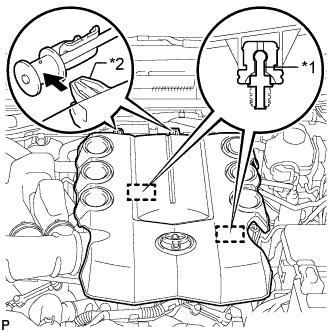
Text in Illustration *1 Pin *2 Hook Attach the 2 V-bank cover hooks to the bracket. Then align the 2 V-bank cover grommets with the 2 pins and press down on the V-bank cover to attach the pins.
-
-
INSTALL UPPER RADIATOR SUPPORT SEAL
-
Install the upper radiator support seal with the 13 clips.
-
-
INSTALL NO. 1 ENGINE UNDER COVER SUB-ASSEMBLY
-
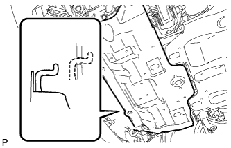
Hook the engine under cover to the vehicle body as shown in the illustration.
-
Install the 4 bolts.
- Torque:
- 29 N*m { 296 kgf*cm, 21 ft.*lbf }
-
-
INSTALL FRONT BUMPER COVER LOWER
-
Install the front bumper cover lower with the 5 bolts and clip.
- Torque:
- 8.0 N*m { 82 kgf*cm, 71 in.*lbf }
-
-
INSPECT IGNITION TIMING
Note
-
Turn all electrical systems off.
-
Perform the inspection when the cooling fan motor is turned off.
-
Warm up the engine.
-
When using the intelligent tester:
-
Connect the intelligent tester to the DLC3.
-
Enter the following menus: Powertrain / Engine and ECT / Data List / All Data / IGN Advance.
-
Inspect the ignition timing during idling.
Standard ignition timing 8 to 12° BTDC @ idle (transmission in neutral and A/C switch off) -
Check that the ignition timing advances immediately when the engine speed is increased.
-
-
When not using the intelligent tester:
-
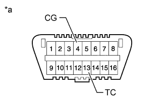
Using SST, connect terminals 13 (TC) and 4 (CG) of the DLC3.
- SST
- 09843-18040
Text in Illustration *a Front view of DLC3 Note
Be sure not to improperly connect the terminals. This may damage the engine.
-
Connect the tester probe of a timing light to the wire of the ignition coil connector for the No. 1 cylinder.
Note
-
Use a timing light that detects primary signals.
-
After the inspection, be sure to wrap the wire harness with tape.
-
-
Inspect the ignition timing during idling.
Standard ignition timing 8 to 12° BTDC @ idle (transmission in neutral and A/C switch off) -
Remove SST from the DLC3.
-
Inspect the ignition timing during idling.
Standard ignition timing 7 to 24° BTDC @ idle (transmission in neutral and A/C switch off) -
Disconnect the timing light from the engine.
-
-