Click here
Click here
Click here
Click here
-
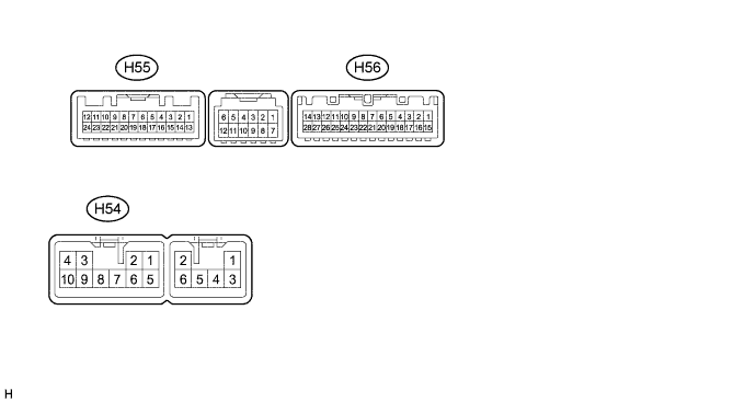
CHECK NAVIGATION RECEIVER ASSEMBLY
-
Disconnect the H54 and H56 navigation receiver assembly connectors.
-
Measure the voltage and resistance according to the value(s) in the table below.
Terminal No. (Symbol) Wiring Color Terminal Description Condition Specification H54-3 (ACC1) - H54-7 (GND1) GR - BR Power source (ACC) Ignition switch off Below 1 V Ignition switch ACC 11 to 14 V H54-4 (+B1) - H54-7 (GND1) R - BR Power source (+B) Always 11 to 14 V H54-7 (GND1) - Body ground BR - Body ground Ground Always Below 1 Ω H56-1 (IG) - H54-7 (GND1) L - BR Power source (IG) Ignition switch off Below 1 V Ignition switch ON 11 to 14 V -
Reconnect the H54 and H56 navigation receiver assembly connectors.
-
Measure the voltage and waveform according to the value(s) in the table below.
Terminal No. (Symbol) Wiring Color Terminal Description Condition Specification H56-2 (REV) - H54-7 (GND1) R - W-B Reverse signal Ignition switch ON, shift lever in R 7.5 to 14 V Ignition switch ON, shift lever not in R Below 1 V H55-11 (CA+) - H55-23 (CGND) B - Shielded Power source Ignition switch ON 5.5 to 7.05 V H55-12 (V+) - H55-23 (CGND) R - Shielded Display signal Ignition switch ON, camera lens not covered, displaying an image Pulse generation (See waveform 1) Ignition switch ON, camera lens covered, blacking out screen Pulse generation (See waveform 2) H55-23 (CGND) - Body ground Shielded - Body ground Shielded ground Always Below 1 V -
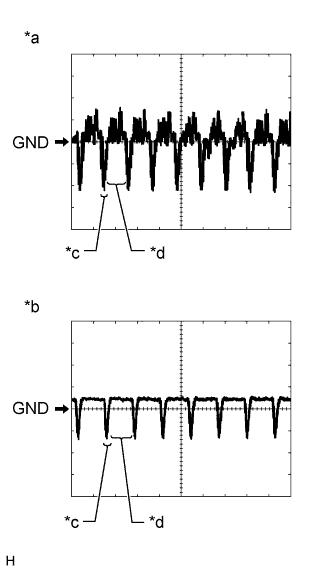
Using an oscilloscope, check the waveform.
-
Waveform 1
Table 1. Measurement Condition Item Content Terminal No. (Symbol) H55-12 (V+) - H55-23 (CGND) Tool Setting 200 mV/DIV., 50 μs/DIV. Condition Ignition switch ON, camera lens not covered, displaying an image Tip:The video waveform changes according to the image sent by the rear television camera assembly.
-
Waveform 2
Table 2. Measurement Condition Item Content Terminal No. (Symbol) H55-12 (V+) - H55-23 (CGND) Tool Setting 200 mV/DIV., 50 μs/DIV. Condition Ignition switch ON, camera lens covered, blacking out screen Tip:The video waveform changes according to the image sent by the rear television camera assembly.
Table 3. Text in Illustration *a Waveform 1 *b Waveform 2 *c Synchronized Signal *d Video Waveform
-
-