DESCRIPTION
This is the display signal circuit between the radio and display receiver assembly and the rear television camera assembly.
INSPECTION PROCEDURE
PROCEDURE
- Click here
CHECK HARNESS AND CONNECTOR (RADIO AND DISPLAY RECEIVER ASSEMBLY - REAR TELEVISION CAMERA ASSEMBLY)
-
Disconnect the H50 radio and display receiver assembly connector.
-
Disconnect the X9*1 or v2*2 rear television camera assembly connector.
-
Measure the resistance according to the value(s) in the table below.
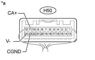
Standard Resistance w/ Tire Carrier Table 1. Tester Connection Condition Specified Condition H50-11 (CA+) - X9-6 (CB+) Always Below 1 Ω H50-12 (V+) - X9-3 (CV+) Always Below 1 Ω H50-23 (CGND) - X9-5 (CGND) Always Below 1 Ω H50-24 (V-) - X9-2 (CV-) Always Below 1 Ω H50-11 (CA+) - Body ground Always 10 kΩ or higher H50-12 (V+) - Body ground Always 10 kΩ or higher H50-23 (CGND) - Body ground Always 10 kΩ or higher H50-24 (V-) - Body ground Always 10 kΩ or higher w/o Tire Carrier Tester Connection Condition Specified Condition H50-11 (CA+) - v2-6 (CB+) Always Below 1 Ω H50-12 (V+) - v2-3 (CV+) Always Below 1 Ω H50-23 (CGND) - v2-5 (CGND) Always Below 1 Ω H50-24 (V-) - v2-2 (CV-) Always Below 1 Ω H50-11 (CA+) - Body ground Always 10 kΩ or higher H50-12 (V+) - Body ground Always 10 kΩ or higher H50-23 (CGND) - Body ground Always 10 kΩ or higher H50-24 (V-) - Body ground Always 10 kΩ or higher
- OKClick here
- NGClick here
-
- Click here
CHECK RADIO AND DISPLAY RECEIVER ASSEMBLY
-
Measure the resistance according to the value(s) in the table below.
Standard Resistance Tester Connection Condition Specified Condition H50-23 (CGND) - Body ground Always Below 1 Ω H50-24 (V-) - Body ground Always Below 1 Ω -
Measure the voltage according to the value(s) in the table below.
Standard Voltage Tester Connection Switch Condition Specified Condition H50-11 (CA+) - Body ground Ignition switch ON 5.5 to 7.05 V Table 2. Text in Illustration *a Component with harness connected
(Radio and Display Receiver Assembly)
Table 3. Result Result Proceed to OK A NG (w/ Navigation System) B NG (w/o Navigation System) C
-
- Click here
CHECK REAR TELEVISION CAMERA ASSEMBLY
-
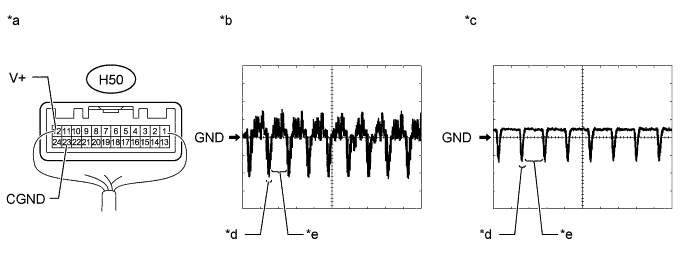
Using an oscilloscope, check the waveform.
Table 4. Text in Illustration *a Component with harness connected
(Radio and Display Receiver Assembly)
*b Waveform 1 *c Waveform 2 *d Synchronized Signal *e Video Waveform - - Table 5. Measurement Condition Item Content Tester Connection H50-12 (V+) - H50-23 (CGND) Tool Setting 200 mV/DIV., 50 μs/DIV. Condition
-
Waveform 1: Ignition switch ON, camera lens not covered, displaying an image
-
Waveform 2: Ignition switch ON, camera lens covered, blacking out screen
OK Waveform is as shown in illustration. Tip:The video waveform changes according to the image sent by the rear television camera assembly.
Table 6. Result Result Proceed to OK A NG (w/ Tire Carrier) B NG (w/o Tire Carrier) C -
-
- Click here
REPAIR OR REPLACE HARNESS OR CONNECTOR
- Click here
REPLACE RADIO AND DISPLAY RECEIVER ASSEMBLYClick here
- Click here
REPLACE REAR TELEVISION CAMERA ASSEMBLYClick here
- Click here
PROCEED TO NEXT SUSPECTED AREA SHOWN IN PROBLEM SYMPTOMS TABLEClick here
- Click here
REPLACE REAR TELEVISION CAMERA ASSEMBLYClick here
- Click here
REPLACE RADIO AND DISPLAY RECEIVER ASSEMBLYClick here