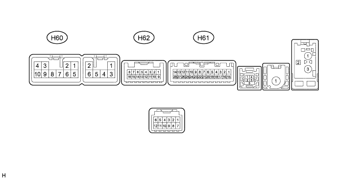
PARKING ASSIST MONITOR SYSTEM (w/o Side Monitor System) TERMINALS OF ECU

-
CHECK NAVIGATION RECEIVER ASSEMBLY
-
Disconnect the H60 and H61 navigation receiver assembly connectors.
-
Measure the voltage and resistance according to the value(s) in the table below.
Terminal No. (Symbol) Wiring Color Terminal Description Condition Specification H60-3 (ACC1) - H60-7 (GND1) GR - BR Power source (ACC) Engine switch off Below 1 V Engine switch on (ACC) 11 to 14 V H60-4 (+B1) - H60-7 (GND1) R - BR Power source (+B) Always 11 to 14 V H60-7 (GND1) - Body ground BR - Body ground Ground Always Below 1 Ω H61-1 (IG) - H60-7 (GND1) L - BR Power source (IG) Engine switch off Below 1 V Engine switch on (IG) 11 to 14 V -
Reconnect the H60 and H61 navigation receiver assembly connectors.
-
Measure the voltage and waveform according to the value(s) in the table below.
Terminal No. (Symbol) Wiring Color Terminal Description Condition Specification H61-2 (REV) - H60-7 (GND1) R - BR Reverse signal Engine switch on (IG), shift lever in R 7.5 to 14 V Engine switch on (IG), shift lever not in R Below 1 V H62-7 (CA+) - H62-15 (CGND) B - Shielded Power source Engine switch on (IG) (ACC) 5.5 to 7.05 V H62-8 (V+) - H62-15 (CGND) R - Shielded Display signal Engine switch on (IG) Pulse generation (See waveform 1) Engine switch on (IG), screen blacked out by covering camera lens Pulse generation (See waveform 2) H62-15 (CGND) - Body ground Shielded - Body ground Shielded ground Always Below 1 V -
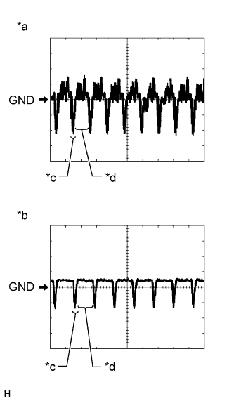
Text in Illustration *a Waveform 1 *b Waveform 2 *c Synchronized Signal *d Video Waveform Using an oscilloscope, check the waveform.
-
Waveform 1
Measurement Condition Item Content Terminal No. (Symbol) H62-8 (V+) - H62-15 (CGND) Tool Setting 0.2 V/DIV., 50 μs/DIV. Condition Engine switch on (IG) Tech Tips
The video waveform changes according to the image sent by the rear television camera assembly.
-
Waveform 2
Measurement Condition Item Content Terminal No. (Symbol) H62-8 (V+) - H62-15 (CGND) Tool Setting 0.2 V/DIV., 50 μs/DIV. Condition Engine switch on (IG), screen blacked out by covering camera lens Tech Tips
The video waveform changes according to the image sent by the rear television camera assembly.
-
-
-
CHECK MAIN BODY ECU (MULTIPLEX NETWORK BODY ECU) Click here