PARKING ASSIST MONITOR SYSTEM (w/o Side Monitor System) Reverse Signal Circuit
DESCRIPTION
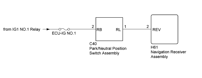
The navigation receiver assembly receives a reverse signal from the park/neutral position switch assembly.
WIRING DIAGRAM
INSPECTION PROCEDURE
Note
Inspect the fuses for circuits related to this system before performing the following inspection procedure.
PROCEDURE
-
CHECK VEHICLE SIGNAL (OPERATION CHECK)
-
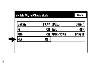
Enter the "Function Check/Setting I" mode and select "Vehicle Signal" Click here.
-
Check that the display changes between ON and OFF according to the shift lever position.
OK Shift Lever Position Display R ON Except R OFF Tech Tips
This display is updated once per second. As a result, it is normal for the display to lag behind the actual shift lever position.
NG 
INSPECT PARK/NEUTRAL POSITION SWITCH ASSEMBLY Click here
OK 
PROCEED TO NEXT SUSPECTED AREA SHOWN IN PROBLEM SYMPTOMS TABLE Click here
-
-
INSPECT PARK/NEUTRAL POSITION SWITCH ASSEMBLY
-
Remove the park/neutral position switch assembly Click here.
-
Inspect the park/neutral position switch assembly Click here.
NG 
REPLACE PARK/NEUTRAL POSITION SWITCH ASSEMBLY Click here
OK 
-
-
CHECK HARNESS AND CONNECTOR (PARK/NEUTRAL POSITION SWITCH ASSEMBLY - BATTERY)
-
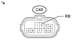
Text in Illustration *a Front view of wire harness connector
(to Park/Neutral Position Switch Assembly)
Disconnect the park/neutral position switch assembly connector.
-
Measure the voltage according to the value(s) in the table below.
Standard Voltage Tester Connection Switch Condition Specified Condition C40-2 (RB) - Body ground Engine switch on (IG) 11 to 14 V Engine switch off Below 1 V
NG
REPAIR OR REPLACE HARNESS OR CONNECTOR
OK
-
-
CHECK HARNESS AND CONNECTOR (NAVIGATION RECEIVER ASSEMBLY - PARK/NEUTRAL POSITION SWITCH ASSEMBLY)
-
Disconnect the H61 navigation receiver assembly connector.
-
Disconnect the C40 park/neutral position switch assembly connector.
-
Measure the resistance according to the value(s) in the table below.
Standard Resistance Tester Connection Condition Specified Condition H61-2 (REV) - C40-1 (RL) Always Below 1 Ω H61-2 (REV) - Body ground Always 10 kΩ or higher
NG
REPAIR OR REPLACE HARNESS OR CONNECTOR
OK
REPLACE NAVIGATION RECEIVER ASSEMBLY Click here
-