DESCRIPTION
The warning indicator lights are installed in the clearance warning indicator assembly.
INSPECTION PROCEDURE
Inspect the fuses for circuits related to this system before performing the following inspection procedure.
PROCEDURE
- Click here
CHECK HARNESS AND CONNECTOR (CLEARANCE WARNING INDICATOR - BATTERY)
-
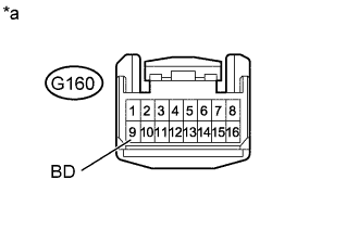
Disconnect the G160 clearance warning indicator assembly connector.
-
Measure the voltage according to the value(s) in the table below.
Standard Voltage Tester Connection Switch Condition Specified Condition G160-9 (BD) - Body ground Ignition switch ON 11 to 14 V Table 1. Text in Illustration *a Front view of wire harness connector
(to Clearance Warning Indicator Assembly)
- OKClick here
- NGClick here
-
- Click here
CHECK HARNESS AND CONNECTOR (CLEARANCE WARNING ECU - CLEARANCE WARNING INDICATOR)
-
Disconnect the I1 clearance warning ECU connector.
-
Disconnect the G160 clearance warning indicator light assembly connector.
-
Measure the resistance according to the value(s) in the table below.
Standard Resistance Tester Connection Condition Specified Condition I1-15 (L1) - G160-5 (RR) Always Below 1 Ω I1-17 (L3) - G160-14 (RL) Always Below 1 Ω I1-19 (L5) - G160-15 (BK) Always Below 1 Ω I1-20 (L6) - G160-1 (OP) Always Below 1 Ω I1-15 (L1) - Body ground Always 10 kΩ or higher I1-17 (L3) - Body ground Always 10 kΩ or higher I1-19 (L5) - Body ground Always 10 kΩ or higher I1-20 (L6) - Body ground Always 10 kΩ or higher
- OKClick here
- NGClick here
-
- Click here
REPAIR OR REPLACE HARNESS OR CONNECTOR
- Click here
PROCEED TO NEXT SUSPECTED AREA SHOWN IN PROBLEM SYMPTOMS TABLEClick here