TOYOTA PARKING ASSIST-SENSOR SYSTEM (w/o Multi-display) Park / Neutral Position Switch Circuit
DESCRIPTION
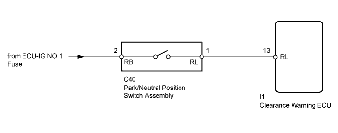
This circuit sends the park/neutral position switch assembly signals to the clearance warning ECU.
WIRING DIAGRAM
INSPECTION PROCEDURE
Note
Inspect the fuses for circuits related to this system before performing the following inspection procedure.
PROCEDURE
-
INSPECT PARK/NEUTRAL POSITION SWITCH ASSEMBLY
-
Disconnect the C40 park/neutral position switch assembly connector.
-
Measure the resistance according to the value(s) in the table below.
Standard Resistance Tester Connection Condition Specified Condition 1 (RL) - 2 (RB) Shift lever in R Below 1 Ω 1 (RL) - 2 (RB) Shift lever not in R 10 kΩ or higher Result Result Proceed to OK A NG (for A750F) B NG (for A343F) C
B 
REPLACE PARK/NEUTRAL POSITION SWITCH ASSEMBLY Click here
C
REPLACE PARK/NEUTRAL POSITION SWITCH ASSEMBLY Click here
A 
-
-
CHECK HARNESS AND CONNECTOR (PARK/NEUTRAL POSITION SWITCH - BATTERY)
-
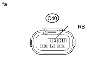
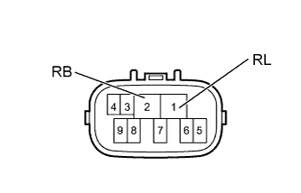
Text in Illustration *a Front view of wire harness connector
(to Park/Neutral Position Switch Assembly)
Disconnect the C40 park/neutral position switch assembly connector.
-
Measure the voltage according to the value(s) in the table below.
Standard Voltage Tester Connection Switch Condition Specified Condition C40-2 (RB) - Body ground Ignition switch ON 11 to 14 V
NG
REPAIR OR REPLACE HARNESS OR CONNECTOR
OK
-
-
CHECK HARNESS AND CONNECTOR (CLEARANCE WARNING ECU - PARK/NEUTRAL POSITION SWITCH)
-
Disconnect the I1 clearance warning ECU connector.
-
Disconnect the C40 park/neutral position switch assembly connector.
-
Measure the resistance according to the value(s) in the table below.
Standard Resistance Tester Connection Condition Specified Condition I1-13 (RL) - C40-1 (RL) Always Below 1 Ω I1-13 (RL) - Body ground Always 10 kΩ or higher
NG
REPAIR OR REPLACE HARNESS OR CONNECTOR
OK 
PROCEED TO NEXT SUSPECTED AREA SHOWN IN PROBLEM SYMPTOMS TABLE Click here
-