TOYOTA PARKING ASSIST-SENSOR SYSTEM (w/ Multi-display) Main Switch Circuit
DESCRIPTION
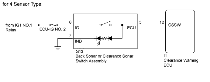
for 4 Sensor Type:
When the back sonar or clearance sonar switch assembly is turned on, the on signal is input into the ECU.
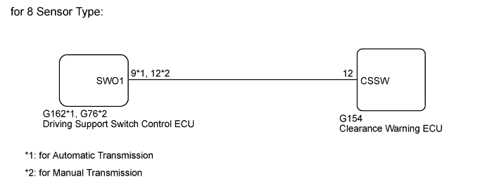
for 8 Sensor Type
When the driving support switch control ECU receives the clearance sonar on/off switch signal, the ECU sends it to the clearance warning ECU.
WIRING DIAGRAM
INSPECTION PROCEDURE
Note
Inspect the fuses for circuits related to this system before performing the following inspection procedure.
PROCEDURE
-
READ VALUE USING GTS
-
Connect the GTS to the DLC3.
-
Turn the engine switch on (IG).
-
Turn the GTS on.
-
Enter the following menus: Body / Clearance Sonar / Data List.
-
According to the display on the GTS, read the Data List.
Clearance Sonar Tester Display Measurement Item/Range Normal Condition Diagnostic Note Main Switch TOYOTA parking assist-sensor system (multi-function switch)/OFF or ON OFF: TOYOTA parking assist-sensor system off
ON: TOYOTA parking assist-sensor system on
- OK The display changes as shown above when the TOYOTA parking assist-sensor system is operated. Result Result Proceed to OK A NG (for 4 Sensor Type) B NG (for 8 Sensor Type) C
B 
INSPECT BACK SONAR OR CLEARANCE SONAR SWITCH ASSEMBLY Click here
C
CHECK HARNESS AND CONNECTOR (DRIVING SUPPORT SWITCH CONTROL ECU - CLEARANCE WARNING ECU) Click here
A 
PROCEED TO NEXT SUSPECTED AREA SHOWN IN PROBLEM SYMPTOMS TABLE Click here
-
-
INSPECT BACK SONAR OR CLEARANCE SONAR SWITCH ASSEMBLY
-
Remove the back sonar or clearance sonar switch assembly Click here.
-
Inspect the back sonar or clearance sonar switch assembly Click here.
NG 
REPLACE BACK SONAR OR CLEARANCE SONAR SWITCH ASSEMBLY Click here
OK 
-
-
CHECK HARNESS AND CONNECTOR (BACK SONAR OR CLEARANCE SONAR SWITCH ASSEMBLY - CLEARANCE WARNING ECU, BATTERY AND BODY GROUND)
-
Disconnect the G13 back sonar or clearance sonar switch assembly connector.
-
Disconnect the I1 clearance warning ECU connector.
-
Measure the resistance according to the value(s) in the table below.
Standard Resistance Tester Connection Switch Condition Specified Condition G13-6 (IG) - Body ground Engine switch on (IG) 11 to 14 V -
Measure the resistance according to the value(s) in the table below.
Standard Resistance Tester Connection Condition Specified Condition G13-3 (ECU) - I1-12 (CSSW) Always Below 1 Ω G13-7 (IND) - Body ground Always Below 1 Ω G13-3 (ECU) - Body ground Always 10 kΩ or higher Result Result Proceed to OK (for LHD) A OK (for RHD) B NG C
B
REPLACE CLEARANCE WARNING ECU Click here
C
REPAIR OR REPLACE HARNESS OR CONNECTOR
A
REPLACE CLEARANCE WARNING ECU Click here
-
-
CHECK HARNESS AND CONNECTOR (DRIVING SUPPORT SWITCH CONTROL ECU - CLEARANCE WARNING ECU)
-
Disconnect the G162*1 or G76*2 driving support switch control ECU connector.
-
*1: for Automatic Transmission
-
*2: for Manual Transmission
-
-
Disconnect the G154 clearance warning ECU connector.
-
Measure the resistance according to the value(s) in the table below.
Standard Resistance for Automatic Transmission Tester Connection Condition Specified Condition G162-9 (SWO1) - G154-12 (CSSW) Always Below 1 Ω G162-9 (SWO1) - Body ground Always 10 kΩ or higher for Manual Transmission Tester Connection Condition Specified Condition G76-12 (SWO1) - G154-12 (CSSW) Always Below 1 Ω G76-12 (SWO1) - Body ground Always 10 kΩ or higher
NG
REPAIR OR REPLACE HARNESS OR CONNECTOR
OK
-
-
CHECK DRIVING SUPPORT SWITCH CONTROL ECU
-
Replace the driving support switch control ECU with a new or normally functioning one Click here.
-
Check the TOYOTA parking assist-sensor system operates normally.
OK TOYOTA parking assist-sensor system operates normally. Result Result Proceed to OK A NG (for LHD) B NG (for RHD) C
B
REPLACE CLEARANCE WARNING ECU Click here
C
REPLACE CLEARANCE WARNING ECU Click here
A
END (DRIVING SUPPORT SWITCH CONTROL ECU IS DEFECTIVE)
-