NAVIGATION SYSTEM (for Navigation Receiver Type), Diagnostic DTC:B158F

| DTC Code | DTC Name |
|---|---|
| B158F | AV Signal Stoppage (Low Battery Voltage) |
DESCRIPTION
This DTC is stored when a video or audio signal is interrupted due to battery voltage input to the navigation receiver assembly dropping temporarily.
| DTC Code | DTC Detection Condition | Trouble Area |
|---|---|---|
| B158F | A video or audio signal is interrupted when the battery voltage drops. |
|
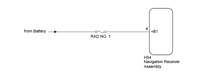
WIRING DIAGRAM
INSPECTION PROCEDURE
Note
Inspect the fuses for circuits related to this system before performing the following procedure.
Tech Tips
When replacing the navigation receiver assembly, it is necessary to perform the vehicle contract setting for Connected Services (w/ Connected Services Function).
PROCEDURE
-
CHECK VEHICLE SIGNAL (OPERATION CHECK)
-
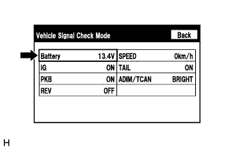
Enter the "Vehicle Signal Check Mode" screen. [Refer to Check Vehicle Signal in Operation Check Click here]
-
Check that the battery voltage.
Standard voltage 11 to 14 V Tech Tips
This display is updated once per second. As a result, it is normal for the display to lag behind the actual switch operation.
NG 
CHECK HARNESS AND CONNECTOR (NAVIGATION RECEIVER ASSEMBLY POWER SOURCE) Click here
OK 
-
-
CHECK FOR DTC
-
Clear the DTCs Click here.
-
Check for DTCs Click here.
OK No DTCs are output.
NG 
REPLACE NAVIGATION RECEIVER ASSEMBLY Click here
OK 
USE SIMULATION METHOD TO CHECK Click here
-
-
CHECK HARNESS AND CONNECTOR (NAVIGATION RECEIVER ASSEMBLY POWER SOURCE)
-
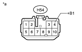
Text in Illustration *a Front view of wire harness connector
(to Navigation Receiver Assembly)
Disconnect the navigation receiver assembly connector.
-
Measure the voltage according to the value(s) in the table below.
Standard Voltage Tester Connection Condition Specified Condition H54-4 (+B1) - Body ground Always 11 to 14 V
NG
REPAIR OR REPLACE HARNESS OR CONNECTOR
OK
REPLACE NAVIGATION RECEIVER ASSEMBLY Click here
-