NAVIGATION SYSTEM (for Navigation Receiver Type), Diagnostic DTC:B1579

| DTC Code | DTC Name |
|---|---|
| B1579 | Voice Recognition Microphone Disconnected |
DESCRIPTION
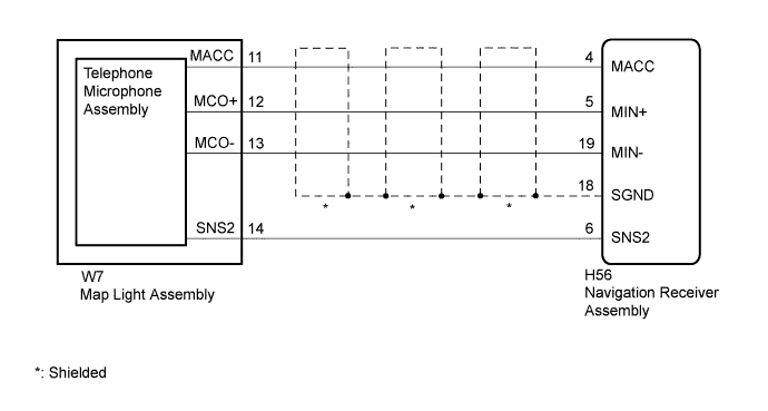
The navigation receiver assembly and map light assembly (telephone microphone assembly) are connected to each other using the microphone connection detection signal lines.
This DTC is stored when a microphone connection detection signal line is disconnected.
| DTC Code | DTC Detection Condition | Trouble Area |
|---|---|---|
| B1579 | Telephone microphone signal is lost. |
|
WIRING DIAGRAM
INSPECTION PROCEDURE
Tech Tips
When replacing the navigation receiver assembly, it is necessary to perform the vehicle contract setting for Connected Services (w/ Connected Services Function).
PROCEDURE
-
CHECK NAVIGATION RECEIVER ASSEMBLY
-
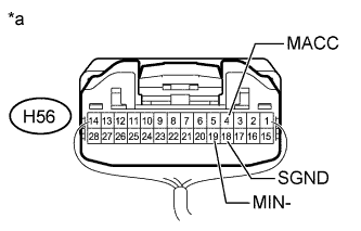
Text in Illustration *a Component with harness connected
(Navigation Receiver Assembly)
Measure the resistance according to the value(s) in the table below.
Standard Resistance Tester Connection Condition Specified Condition H56-18 (SGND) - Body ground Always Below 1 Ω H56-19 (MIN-) - Body ground Always Below 1 Ω -
Measure the voltage according to the value(s) in the table below.
Standard Voltage Tester Connection Switch Condition Specified Condition H56-4 (MACC) - Body ground Engine switch on (ACC) 4 to 6 V
NG 
REPLACE NAVIGATION RECEIVER ASSEMBLY Click here
OK 
-
-
CHECK HARNESS AND CONNECTOR (NAVIGATION RECEIVER ASSEMBLY - MAP LIGHT ASSEMBLY)
-
Disconnect the H56 navigation receiver assembly connector.
-
Disconnect the W7 map light assembly connector.
-
Measure the resistance according to the value(s) in the table below.
Standard Resistance Tester Connection Condition Specified Condition H56-4 (MACC) - W7-11 (MACC) Always Below 1 Ω H56-5 (MIN+) - W7-12 (MCO+) Always Below 1 Ω H56-19 (MIN-) - W7-13 (MCO-) Always Below 1 Ω H56-6 (SNS2) - W7-14 (SNS2) Always Below 1 Ω H56-4 (MACC) - Body ground Always 10 kΩ or higher H56-5 (MIN+) - Body ground Always 10 kΩ or higher H56-19 (MIN-) - Body ground Always 10 kΩ or higher H56-18 (SGND) - Body ground Always 10 kΩ or higher H56-6 (SNS2) - Body ground Always 10 kΩ or higher
NG
REPAIR OR REPLACE HARNESS OR CONNECTOR
OK
-
-
CHECK TELEPHONE MICROPHONE ASSEMBLY
-
Replace the telephone microphone assembly with a known good one Click here.
-
Check for DTCs Click here.
OK No DTCs are output.
NG
REPLACE MAP LIGHT ASSEMBLY Click here
OK 
END (TELEPHONE MICROPHONE ASSEMBLY IS DEFECTIVE)
-