CLEARANCE WARNING ECU (for RHD) INSTALLATION

-
INSTALL CLEARANCE WARNING ECU ASSEMBLY (for 4 Sensor Type)
-
Install the clearance warning ECU assembly with the bolt.
-
Connect the connector.
-
-
INSTALL DRIVER SIDE JUNCTION BLOCK ASSEMBLY (for 4 Sensor Type)
-
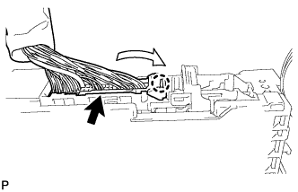
Attach the claw to install the connector as shown in the illustration.
Note
Be sure to connect each connector securely.
-
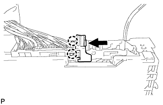
Attach the 2 claws to lock the connector lock as shown in the illustration.
-
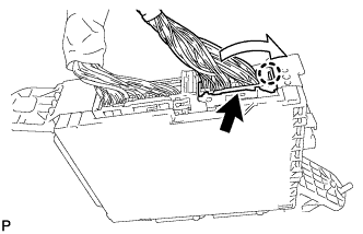
Attach the claw to connect the connector as shown in the illustration.
Note
Be sure to connect the connector securely.
-
Install the driver side junction block assembly with the bolt and 2 nuts.
- Torque:
- 8.0 N*m { 82 kgf*cm, 71 in.*lbf }
-
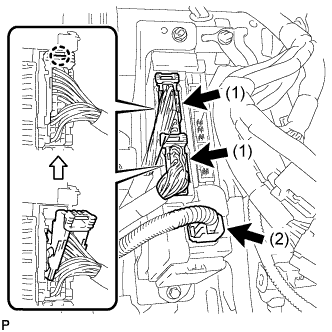
Connect the connector labeled (1).
Note
Be sure to connect each connector securely.
-
Attach the 2 claws to connect the 2 connectors labeled (2) as shown in the illustration.
Note
Be sure to connect each connector securely.
-
Connect the 3 connectors.
Note
Be sure to connect each connector securely.
-
-
INSTALL LOWER NO. 1 INSTRUMENT PANEL AIRBAG ASSEMBLY (for 4 Sensor Type)
-
Install the lower No. 1 instrument panel airbag assembly with the 4 bolts.
-
Connect the connector.
Note
When handling the airbag connector, take care not to damage the airbag wire harness.
- Torque:
- 10 N*m { 102 kgf*cm, 7 ft.*lbf }
-
-
INSTALL LOWER INSTRUMENT PANEL FINISH PANEL SUB-ASSEMBLY (for 4 Sensor Type)
-
Connect each connector and each cable.
-
Attach the 14 clips to install the lower instrument panel finish panel sub-assembly.
-
Install the 2 bolts.
-
Attach the 2 claws to close the cover.
-
-
INSTALL NO. 2 INSTRUMENT PANEL UNDER COVER SUB-ASSEMBLY (for 4 Sensor Type)
-
Attach the 3 clips and 2 guides to install the No. 2 instrument panel under cover.
-
Install the screw.
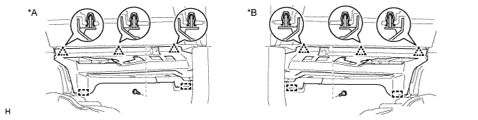
Text in Illustration *A for LHD *B for RHD
-
-
INSTALL INSTRUMENT PANEL FINISH PLATE GARNISH (for 4 Sensor Type)
-
Connect each connector.
-
Attach the 4 clips to install the instrument panel finish plate garnish.
-
-
INSTALL LOWER INSTRUMENT PANEL FINISH PANEL ASSEMBLY (for 4 Sensor Type)
-
Connect each connector.
-
Attach the 4 clips to install the lower instrument panel finish panel assembly.
-
-
INSTALL INSTRUMENT SIDE PANEL RH (for 4 Sensor Type)
-
Attach the 5 clips, claw and 3 guides to install the instrument side panel RH.
-
-
INSTALL COWL SIDE TRIM BOARD RH (for 4 Sensor Type)
-
Attach the clip and claw to install the cowl side trim board RH.
-
Install the clip.
-
-
INSTALL DOOR SCUFF PLATE ASSEMBLY RH (for 4 Sensor Type)
-
Attach the 4 clips, 10 claws and 2 guides to install the door scuff plate assembly RH.
-
-
INSTALL CLEARANCE WARNING ECU ASSEMBLY (for 8 Sensor Type)
-
Install the clearance warning ECU assembly with the 2 nuts.
-
Connect the connector.
-
-
INSTALL GLOVE COMPARTMENT DOOR ASSEMBLY (for 8 Sensor Type)
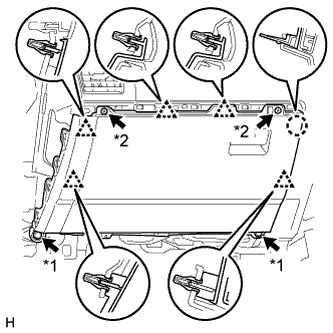
Text in Illustration *1 Bolt *2 Screw
-
Connect each connector.
-
Attach the 5 clips and claw to install the glove compartment door assembly.
-
Install the 2 bolts and 2 screws.
-
-
INSTALL NO. 2 INSTRUMENT PANEL UNDER COVER SUB-ASSEMBLY (for 8 Sensor Type)
-
Attach the 3 clips and 2 guides to install the No. 2 instrument panel under cover.
-
Install the screw.
Text in Illustration *A for LHD *B for RHD
-
-
INSTALL INSTRUMENT PANEL ORNAMENT (for 8 Sensor Type)
-
Attach the 5 clips to install the instrument panel ornament.
-
-
INSTALL INSTRUMENT SIDE PANEL LH (for 8 Sensor Type)
-
Attach the 5 clips, claw and 3 guides to install the instrument side panel LH.
-
-
INSTALL COWL SIDE TRIM BOARD LH (for 8 Sensor Type)
-
Attach the clip and claw to install the cowl side trim board LH.
-
Install the clip.
-
-
INSTALL DOOR SCUFF PLATE ASSEMBLY LH (for 8 Sensor Type)
-
Attach the 4 clips, 10 claws and 2 guides to install the door scuff plate assembly LH.
-
-
CONNECT CABLE TO NEGATIVE BATTERY TERMINAL (for 4 Sensor Type)
Note
When disconnecting the cable, some systems need to be initialized after the cable is reconnected Click here.
-
CHECK SRS WARNING LIGHT (for 4 Sensor Type)