- Click here
PRECAUTION
Note:After turning the ignition switch off, waiting time may be required before disconnecting the cable from the battery terminal. Therefore, make sure to read the disconnecting the cable from the battery terminal notice before proceeding with work (Click here).
- Click here
DISCONNECT CABLE FROM NEGATIVE BATTERY TERMINAL (for 4 Sensor Type)
CAUTION:Wait at least 90 seconds after disconnecting the cable from the negative (-) battery terminal to disable the SRS system.
Note:When disconnecting the cable, some systems need to be initialized after the cable is reconnected (Click here).
-
Click here
REMOVE DOOR SCUFF PLATE ASSEMBLY RH (for 4 Sensor Type)
-
Put protective tape around the door scuff plate assembly RH.
-
Using a screwdriver, detach the 4 clips, 10 claws and 2 guides and remove the door scuff plate assembly RH.
Tip:Tape the screwdriver tip before use.
Table 1. Text in Illustration *1 Protective Tape
-
-
Click here
REMOVE COWL SIDE TRIM BOARD RH (for 4 Sensor Type)
-
Remove the clip.
-
Detach the clip and claw and remove the cowl side trim board RH.
-
-
Click here
REMOVE INSTRUMENT SIDE PANEL RH (for 4 Sensor Type)
-
Put protective tape around the instrument side panel RH.
Table 2. Text in Illustration *1 Protective Tape -
Using a moulding remover, detach the 5 clips, claw and 3 guides and remove the instrument side panel RH.
-
-
Click here
REMOVE LOWER INSTRUMENT PANEL FINISH PANEL ASSEMBLY (for 4 Sensor Type)
-
Detach the 4 clips.
-
Disconnect each connector and remove the lower instrument panel finish panel assembly.
-
-
Click here
REMOVE INSTRUMENT PANEL FINISH PLATE GARNISH (for 4 Sensor Type)
-
Detach the 4 clips.
-
Disconnect each connector and remove the instrument panel finish plate garnish.
-
-
Click here
REMOVE NO. 1 INSTRUMENT PANEL UNDER COVER SUB-ASSEMBLY (for 4 Sensor Type)
-
for LHD:
-
Remove the screw.
-
Detach the 2 clips and 2 guides and remove the No. 1 instrument panel under cover.
-
Disconnect each connector.
-
-
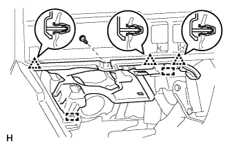
for RHD:
-
Remove the screw.
-
Detach the 3 clips and 2 guides and remove the No. 1 instrument panel under cover.
-
Disconnect each connector.
-
-
- Click here
REMOVE LOWER INSTRUMENT PANEL FINISH PANEL SUB-ASSEMBLY (for 4 Sensor Type)
-
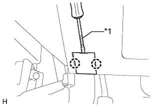
Using a screwdriver, detach the 2 claws and open the cover.
Tip:Tape the screwdriver tip before use.
Table 3. Text in Illustration *1 Protective Tape -
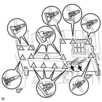
Remove the 2 bolts.
-
Detach the 14 clips.
-
Disconnect each connector and each cable and remove the lower instrument panel finish panel sub-assembly.
-
-
Click here
REMOVE LOWER NO. 1 INSTRUMENT PANEL AIRBAG ASSEMBLY (for 4 Sensor Type)
-
Disconnect the connector.
-
Remove the 4 bolts and lower No. 1 instrument panel airbag assembly.
Note:When handling the airbag connector, take care not to damage the airbag wire harness.
-
- Click here
REMOVE DRIVER SIDE JUNCTION BLOCK ASSEMBLY (for 4 Sensor Type)
-
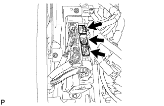
Disconnect the 3 connectors.
-
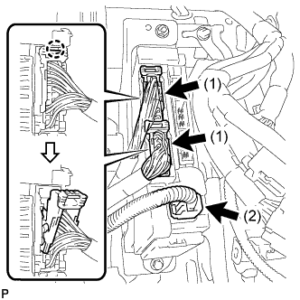
Detach the 2 claws and disconnect the 2 connectors labeled (1) as shown in the illustration.
-
Disconnect the connector labeled (2).
-
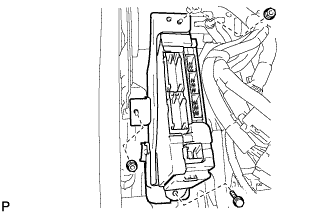
Remove the bolt and 2 nuts and disconnect the driver side junction block assembly.
-
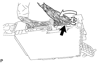
Detach the claw and disconnect the connector as shown in the illustration.
-
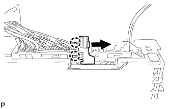
Detach the 2 claws and release the connector's lock as shown in the illustration.
-
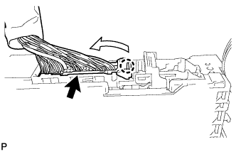
Detach the claw and disconnect the connector as shown in the illustration.
-
Remove the driver side junction block assembly.
-
-
Click here
REMOVE CLEARANCE WARNING ECU ASSEMBLY (for 4 Sensor Type)
-
Disconnect the connector.
-
Remove the bolt and clearance warning ECU assembly.
-
-
Click here
REMOVE DOOR SCUFF PLATE ASSEMBLY LH (for 8 Sensor Type)
-
Put protective tape around the door scuff plate assembly LH.
-
Using a screwdriver, detach the 4 clips, 10 claws and 2 guides and remove the door scuff plate assembly LH.
Tip:Tape the screwdriver tip before use.
Table 4. Text in Illustration *1 Protective Tape
-
-
Click here
REMOVE COWL SIDE TRIM BOARD LH (for 8 Sensor Type)
-
Remove the clip.
-
Detach the clip and claw and remove the cowl side trim board LH.
-
-
Click here
REMOVE INSTRUMENT SIDE PANEL LH (for 8 Sensor Type)
-
Put protective tape around the instrument side panel LH.
Table 5. Text in Illustration *1 Protective Tape -
Using a moulding remover, detach the 5 clips, claw and 3 guides and remove the instrument side panel LH.
-
-
Click here
REMOVE INSTRUMENT PANEL ORNAMENT (for 8 Sensor Type)
-
Put protective tape around the instrument panel ornament.
Table 6. Text in Illustration *1 Protective Tape -
Using a moulding remover, detach the 5 clips and remove the instrument panel ornament.
-
- Click here
REMOVE NO. 2 INSTRUMENT PANEL UNDER COVER SUB-ASSEMBLY (for 8 Sensor Type)
-
Remove the screw.
-
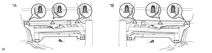
Detach the 3 clips and 2 guides and remove the No. 2 instrument panel under cover.
Table 7. Text in Illustration *A for LHD *B for RHD
-
-
Click here
REMOVE GLOVE COMPARTMENT DOOR ASSEMBLY (for 8 Sensor Type)
-
Remove the 2 bolts and 2 screws.
Table 8. Text in Illustration *1 Bolt *2 Screw -
Detach the 5 clips and claw.
-
Disconnect each connector and remove the glove compartment door assembly.
-
-
Click here
REMOVE CLEARANCE WARNING ECU ASSEMBLY (for 8 Sensor Type)
-
Disconnect the connector.
-
Remove the 2 nuts and clearance warning ECU assembly.
-