COMPRESSOR (for 2AR) INSTALLATION

-
ADJUST COMPRESSOR OIL LEVEL
-
When replacing the compressor with a new one:
-
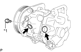
Text in Illustration *1 Drain bolt (washer) Remove the drain bolt (washer).
-
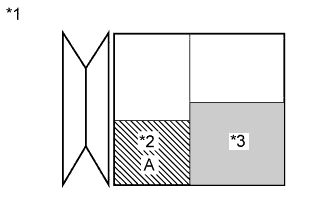
Text in Illustration *1 Removed Compressor *2 Amount of oil drain from removed compressor *3 Amount of oil remaining in the reserve chamber (60 cc (3.66 fl.oz)) Gradually discharge the inert gas from the service valve. Then drain the following amount of oil from the new compressor before installation so that the amount of oil contained in it is the same as that in the compressor to be replaced.
Tech Tips
New compressors are filled with sufficient oil for the whole air conditioning system. Therefore, it is necessary to drain oil from the new compressor to compensate for oil remaining in the condenser and cooling unit.
Standard (The amount of oil inside a new compressor: 100 (+15) cc (6.10 (+0.92) fl.oz)) - (The amount of oil remaining in the old compressor A + oil remaining in the reserve chamber: 60 cc (3.66 fl.oz)) = (The amount of oil to be removed from the new compressor) Note
-
When A + 60 cc (3.66 fl.oz) exceeds the standard oil fill volume specified for the compressor by part number, install the compressor without adjusting the oil volume.
Example:
If A = 45 cc (2.75 fl.oz), A + 60 cc (3.66 fl.oz) = 105 cc (6.41 fl.oz). If the standard volume is 100 cc (6.10 fl.oz), install the compressor as is.
-
When checking the compressor oil level, observe the precautions for cooler removal/installation.
-
If the amount of oil remaining in the removed compressor is too low, check for oil leaks.
-
Use ND-OIL8 or equivalent for compressor oil.
-
-
Install the drain bolt (washer).
- Torque:
- 30 N*m { 306 kgf*cm, 22 ft.*lbf }
-
-
If draining the oil is difficult, drain the oil using the following procedure:
-
Remove the suction seal cap.
-
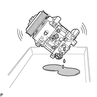
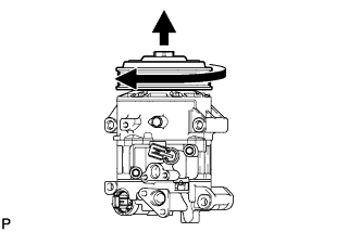
Lightly shake the compressor with the suction port facing down, and drain the oil (*1).
Note
Do not allow the pulley to come into contact with the compressor oil.
-
-
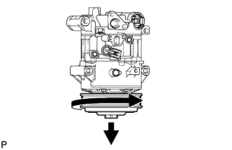
With the DL pulley facing down, rotate the pulley in the direction shown by the arrow 10 times at a rate of approximately once every 2 seconds (*2).
CAUTION:
If the pulley is rotated, refrigerant or oil might splash out. Thus, keep your face away from the compressor port.
-
Rotate the pulley once in the direction shown by the arrow while quickly turning the compressor so the pulley is up (*3).
-
Proceed with the above procedure (*1) and drain the oil (*4).
-
Drain the oil by repeating the procedures above approximately 5 times (from (*2) to (*4)).
-
-
INSTALL COMPRESSOR ASSEMBLY WITH PULLEY
-
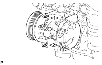
Using an E8 "TORX" socket, temporarily install the compressor assembly with pulley with the 2 stud bolts.
- Torque:
- 10 N*m { 102 kgf*cm, 7 ft.*lbf }
Tech Tips
Tighten the stud bolts in the order shown in the illustration.
-
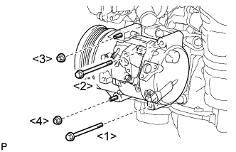
Install the compressor assembly with pulley with the 2 bolts and 2 nuts.
- Torque:
- 25 N*m { 250 kgf*cm, 18 ft.*lbf }
Tech Tips
Tighten the bolts and nuts in the order shown in the illustration to install the compressor.
-
-
INSTALL NO. 1 COOLER REFRIGERANT DISCHARGE HOSE
-
Remove the attached vinyl tape from the hose.
-
Apply sufficient compressor oil to a new O-ring and the fitting surface of the compressor and pulley.
Compressor oil ND-OIL 8 or equivalent -
Install the O-ring to the No. 1 cooler refrigerant discharge hose.
-
Install the No. 1 cooler refrigerant discharge hose onto the compressor and pulley with the bolt.
- Torque:
- 9.8 N*m { 100 kgf*cm, 87 in.*lbf }
-
-
INSTALL SUCTION HOSE SUB-ASSEMBLY (for TMMK Made)
-
Remove the attached vinyl tape from the hose.
-
Apply sufficient compressor oil to a new O-ring and the fitting surface of the compressor and pulley.
Compressor oil ND-OIL 8 or equivalent -
Install the O-ring onto the suction hose sub-assembly.
-
Install the suction hose sub-assembly onto the compressor assembly with pulley with the bolt.
- Torque:
- 9.8 N*m { 100 kgf*cm, 87 in.*lbf }
-
Connect the 2 connectors.
-
Install the bolt.
- Torque:
- 8.0 N*m { 82 kgf*cm, 71 in.*lbf }
-
-
INSTALL NO. 1 COOLER REFRIGERANT SUCTION HOSE (for SIA Made)
-
Remove the attached vinyl tape from the hose.
-
Apply sufficient compressor oil to a new O-ring and the fitting surface of the compressor and pulley.
Compressor oil ND-OIL 8 or equivalent -
Install the O-ring onto the No. 1 cooler refrigerant suction hose.
-
Install the No. 1 cooler refrigerant suction hose onto the compressor assembly with pulley with the bolt.
- Torque:
- 9.8 N*m { 100 kgf*cm, 87 in.*lbf }
-
Connect the 2 connectors.
-
Install the bolt.
- Torque:
- 8.0 N*m { 82 kgf*cm, 71 in.*lbf }
-
-
INSTALL V-RIBBED BELT
-
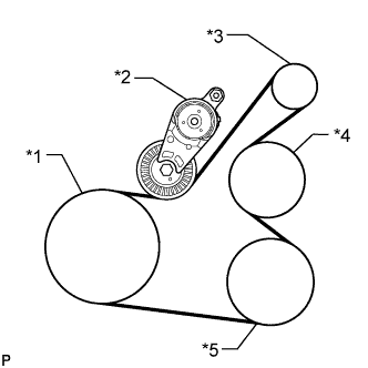
Text in Illustration *1 Crankshaft *2 Tensioner *3 Generator *4 Water Pump *5 Cooler Compressor Set the V-ribbed belt onto each part as shown in the illustration except the water pump pulley.
-
Loosen the V-ribbed belt by turning the belt tensioner clockwise.
-
Set the V-ribbed belt onto the water pump pulley.
Note
Make sure that the belt is attached to each pulley. In particular, make sure that the belt is securely fitted into the grooves of the crankshaft pulley.
-
-
INSTALL FRONT FENDER APRON SEAL RH
-
INSTALL RADIATOR ASSEMBLY
-
CHARGE AIR CONDITIONING SYSTEM WITH REFRIGERANT
-
Perform vacuum purging using a vacuum pump or appropriate equipment.
-
Charge the air conditioning system with refrigerant.
Refrigerant type HFC-134a (R134a) 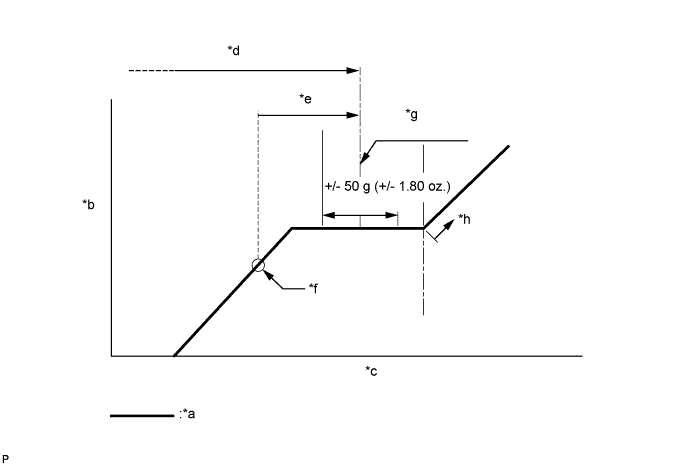
Text in Illustration *a Sub-cool System *b High Pressure *c Refrigerant Amount *d Standard charge amount *e Charge additional 100g (3.5oz.) *f Point where bubbles disappear *g Mean value in proper range *h Overcharged Standard charge amount 480 to 580g (16.9 to 20.4oz.) - SST
- 09985-20010 ( 09985-02010, 09985-02050, 09985-02060, 09985-02070, 09985-02080, 09985-02090, 09985-02110, 09985-02130, 09985-02140, 09985-02150 )
Note
-
Do not turn the A/C switch on before charging the air conditioning system with refrigerant. Doing so may cause the compressor to work without refrigerant, resulting in overheating of the compressor.
-
The refrigerant amount should be checked by quantity (weight).
-
The graph above is shown for reference only. This vehicle is not equipped with a sight glass.
Tech Tips
Ensure that sufficient refrigerant is available to recharge the system when using a refrigerant recovery unit. Refrigerant recovery units are not always able to recover 100% of the refrigerant from an air conditioning system.
-
-
WARM UP ENGINE
-
Keep the A/C switch on for at least 2 minutes to warm up the compressor.
Note
To prevent damage to the compressor, be sure to warm up the compressor when turning the air conditioning on after removing and installing air conditioning system lines (including the compressor).
-
-
INSPECT FOR REFRIGERANT LEAK
-
After recharging the air conditioning system with refrigerant, inspect for refrigerant leaks using a halogen leak detector.
-
Carry out the test under the following conditions:
-
Ignition switch off.
-
Secure good ventilation (the halogen leak detector may react to volatile gases which are not refrigerant, such as gasoline vapor and exhaust gas).
-
Repeat the inspection 2 or 3 times.
-
Measure the pressure to make sure that there is some refrigerant remaining in the air conditioning system.
Pressure when the compressor is off: approx. 392 to 588 kPa (4.0 to 6.0 kgf/cm2, 57 to 85 psi)
-
-
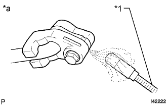
Text in Illustration *1 Halogen Leak Detector *a Inspect for Leak Using a halogen leak detector, inspect for refrigerant leaks from the air conditioning system.
-
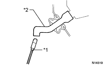
Text in Illustration *1 Halogen Leak Detector *2 Drain Hose Bring the halogen leak detector close to the drain hose with the detector power off, and then turn the detector on.
Tech Tips
-
After the blower motor has stopped, leave the cooling unit for more than 15 minutes.
-
Bring the halogen leak detector sensor under the drain hose.
-
When bringing the halogen leak detector close to the drain hose, make sure that the halogen leak detector does not react to volatile gases. If it is not possible to avoid interference from volatile gases, the vehicle should be lifted up to allow checking for leaks.
-
-
If a refrigerant leak is not detected from the drain hose, remove the blower motor control from the cooling unit. Insert the halogen leak detector sensor into the unit and check for a leak.
-
Disconnect the pressure sensor connector and leave it for approximately 20 minutes. Bring the halogen leak detector close to the pressure sensor and check for a leak.
Tech Tips
When checking for leaks, the presence of oily dirt at a joint can indicate a leak.
-