OCCUPANT CLASSIFICATION SYSTEM, Diagnostic DTC:B1790

| DTC Code | DTC Name |
|---|---|
| B1790 | Center Airbag Sensor Assembly Communication Circuit Malfunction |
DESCRIPTION
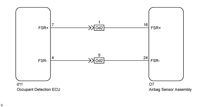
The airbag sensor assembly communication circuit consists of the occupant detection ECU and airbag sensor assembly.
DTC B1790 is stored when a malfunction is detected in the airbag sensor assembly communication circuit.
| DTC No. | DTC Detection Condition | Trouble Area |
|---|---|---|
| B1790 |
|
|
Tech Tips
When DTC B1650/32 is detected as a result of troubleshooting for the airbag system, check the DTCs stored in the occupant detection ECU. When DTC B1790 is output, perform troubleshooting for the DTC.
WIRING DIAGRAM
INSPECTION PROCEDURE
Note
After turning the ignition switch off, waiting time may be required before disconnecting the cable from the negative (-) battery terminal. Therefore, make sure to read the disconnecting the cable from the negative (-) battery terminal notices before proceeding with work Click here.
Tech Tips
-
If troubleshooting (wire harness inspection) is difficult to perform, remove the front passenger seat installation bolts to see under the seat cushion.
-
In the above case, lift and hold the seat so that it does not fall down. Hold the seat only as necessary because holding the seat for a long period of time may cause seat rail deformation.
PROCEDURE
-
CHECK CONNECTORS
-
Turn the ignition switch off.
-
Disconnect the cable from the negative (-) battery terminal.
CAUTION:
Wait at least 90 seconds after disconnecting the cable from the negative (-) battery terminal to disable the SRS system.
-
Check that the connectors are properly connected to the airbag sensor assembly and occupant detection ECU. Also check that the connectors that link the front seat wire RH and No. 2 floor wire are properly connected.
OK The connectors are properly connected. Tech Tips
If the connectors are not connected securely, reconnect the connectors and proceed to the next inspection.
-
Disconnect the connectors from the airbag sensor assembly and occupant detection ECU. Also disconnect the connectors that link the front seat wire RH and No. 2 floor wire.
-
Check that the terminals of the connectors are not damaged.
OK The terminals are not deformed or damaged.
NG 
REPLACE WIRE HARNESS
OK 
-
-
CHECK OCCUPANT CLASSIFICATION SYSTEM CIRCUIT (SHORT TO B+)
-
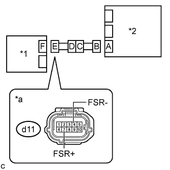
Text in Illustration *1 Occupant Detection ECU *2 Airbag Sensor Assembly *a Front view of wire harness connector
(to Occupant Detection ECU)
Connect the connectors that link the No. 2 floor wire and front seat wire RH.
-
Connect the cable to the negative (-) battery terminal.
-
Turn the ignition switch to ON.
-
Measure the voltage according to the value(s) in the table below.
Standard Voltage Tester Connection Condition Specified Condition d11-7 (FSR+) - Body ground Ignition switch ON Below 1 V d11-4 (FSR-) - Body ground Ignition switch ON Below 1 V -
Turn the ignition switch off.
-
Disconnect the cable from the negative (-) battery terminal.
CAUTION:
Wait at least 90 seconds after disconnecting the cable from the negative (-) battery terminal to disable the SRS system.
NG 
CHECK NO. 2 FLOOR WIRE (SHORT TO B+) Click here
OK
-
-
CHECK OCCUPANT CLASSIFICATION SYSTEM CIRCUIT (OPEN)
-
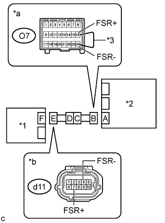
Text in Illustration *1 Occupant Detection ECU *2 Airbag Sensor Assembly *3 Service Wire *a Front view of wire harness connector
(to Airbag Sensor Assembly)
*b Front view of wire harness connector
(to Occupant Detection ECU)
Using a service wire, connect terminals 16 (FSR+) and 24 (FSR-) of connector B.
Note
Do not forcibly insert the service wire into the terminals of the connector when connecting the wire.
-
Measure the resistance according to the value(s) in the table below.
Standard Resistance Tester Connection Condition Specified Condition d11-7 (FSR+) - d11-4 (FSR-) Always Below 1 Ω
NG
CHECK NO. 2 FLOOR WIRE (OPEN) Click here
OK
-
-
CHECK OCCUPANT CLASSIFICATION SYSTEM CIRCUIT (SHORT)
-
Text in Illustration *1 Occupant Detection ECU *2 Airbag Sensor Assembly *a Front view of wire harness connector
(to Occupant Detection ECU)
Disconnect the service wire from connector B.
-
Measure the resistance according to the value(s) in the table below.
Standard Resistance Tester Connection Condition Specified Condition d11-7 (FSR+) - d11-4 (FSR-) Always 1 MΩ or higher
NG
CHECK NO. 2 FLOOR WIRE (SHORT) Click here
OK
-
-
CHECK OCCUPANT CLASSIFICATION SYSTEM CIRCUIT (SHORT TO GROUND)
-
Text in Illustration *1 Occupant Detection ECU *2 Airbag Sensor Assembly *a Front view of wire harness connector
(to Occupant Detection ECU)
Measure the resistance according to the value(s) in the table below.
Standard Resistance Tester Connection Condition Specified Condition d11-7 (FSR+) - Body ground Always 1 MΩ or higher d11-4 (FSR-) - Body ground Always 1 MΩ or higher
NG
CHECK NO. 2 FLOOR WIRE (SHORT TO GROUND) Click here
OK
-
-
CHECK DTC
-
Connect the connectors to the occupant detection ECU and airbag sensor assembly.
-
Connect the cable to the negative (-) battery terminal.
-
Clear the DTCs stored in the occupant detection ECU Click here.
-
Clear the DTCs stored in the airbag sensor assembly Click here.
-
Turn the ignition switch off.
-
Turn the ignition switch to ON.
-
Check for DTCs Click here.
OK DTC B1790 is not output. Tech Tips
Codes other than DTC B1790 may be output at this time, but they are not related to this check.
-
Turn the ignition switch off.
NG
CHECK OCCUPANT DETECTION ECU Click here
OK 
USE SIMULATION METHOD TO CHECK Click here
-
-
CHECK OCCUPANT DETECTION ECU
-
Disconnect the cable from the negative (-) battery terminal.
-
Replace the occupant detection ECU with a known good one Click here.
Tech Tips
Perform the following inspection using known good parts from another vehicle if possible.
-
Connect the cable to the negative (-) battery terminal.
-
Clear the DTCs stored in the occupant detection ECU Click here.
-
Clear the DTCs stored in the airbag sensor assembly Click here.
-
Turn the ignition switch off.
-
Turn the ignition switch to ON.
-
Check for DTCs Click here.
OK DTC B1790 is not output. Tech Tips
Codes other than DTC B1790 may be output at this time, but they are not related to this check.
-
Turn the ignition switch off.
-
Disconnect the cable from the negative (-) battery terminal.
-
Restore the occupant detection ECU that was installed for testing to its original location Click here.
NG
REPLACE AIRBAG SENSOR ASSEMBLY Click here
OK
-
-
REPLACE OCCUPANT DETECTION ECU
-
Disconnect the cable from the negative (-) battery terminal.
-
Replace the occupant detection ECU with a new one Click here.
-
Connect the cable to the negative (-) battery terminal.
NEXT
-
-
PERFORM ZERO POINT CALIBRATION AND SENSITIVITY CHECK
-
Using the Techstream, perform Zero Point Calibration and Sensitivity Check Click here.
NEXT
END
-
-
CHECK NO. 2 FLOOR WIRE (SHORT TO B+)
-
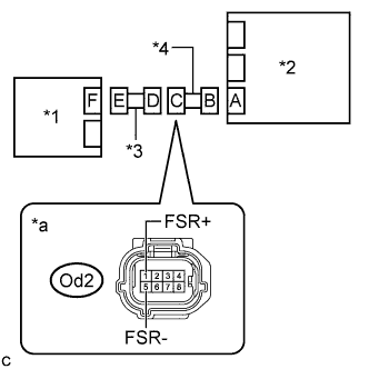
Text in Illustration *1 Occupant Detection ECU *2 Airbag Sensor Assembly *3 Front Seat Wire RH *4 No. 2 Floor Wire *a Front view of wire harness connector
(to Front Seat Wire RH)
Disconnect the front seat wire RH connector from the No. 2 floor wire.
-
Connect the cable to the negative (-) battery terminal.
-
Turn the ignition switch to ON.
-
Measure the voltage according to the value(s) in the table below.
Standard Voltage Tester Connection Condition Specified Condition Od2-1 (FSR+) - Body ground Ignition switch ON Below 1 V Od2-5 (FSR-) - Body ground Ignition switch ON Below 1 V
NG
REPLACE NO. 2 FLOOR WIRE
OK
REPLACE FRONT SEAT WIRE RH
-
-
CHECK NO. 2 FLOOR WIRE (OPEN)
-
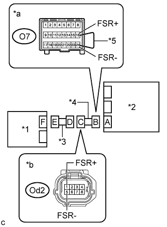
Text in Illustration *1 Occupant Detection ECU *2 Airbag Sensor Assembly *3 Front Seat Wire RH *4 No. 2 Floor Wire *5 Service Wire *a Front view of wire harness connector
(to Airbag Sensor Assembly)
*b Front view of wire harness connector
(to Front Seat Wire RH)
Disconnect the front seat wire RH connector from the No. 2 floor wire.
Tech Tips
The service wire has already been inserted into connector B.
-
Measure the resistance according to the value(s) in the table below.
Standard Resistance Tester Connection Condition Specified Condition Od2-1 (FSR+) - Od2-5 (FSR-) Always Below 1 Ω -
Disconnect the service wire from connector B.
NG
REPLACE NO. 2 FLOOR WIRE
OK
REPLACE FRONT SEAT WIRE RH
-
-
CHECK NO. 2 FLOOR WIRE (SHORT)
-
Text in Illustration *1 Occupant Detection ECU *2 Airbag Sensor Assembly *3 Front Seat Wire RH *4 No. 2 Floor Wire *a Front view of wire harness connector
(to Front Seat Wire RH)
Disconnect the front seat wire RH connector from the No. 2 floor wire.
-
Measure the resistance according to the value(s) in the table below.
Standard Resistance Tester Connection Condition Specified Condition Od2-1 (FSR+) - Od2-5 (FSR-) Always 1 MΩ or higher
NG
REPLACE NO. 2 FLOOR WIRE
OK
REPLACE FRONT SEAT WIRE RH
-
-
CHECK NO. 2 FLOOR WIRE (SHORT TO GROUND)
-
Text in Illustration *1 Occupant Detection ECU *2 Airbag Sensor Assembly *3 Front Seat Wire RH *4 No. 2 Floor Wire *a Front view of wire harness connector
(to Front Seat Wire RH)
Disconnect the front seat wire RH connector from the No. 2 floor wire.
-
Measure the resistance according to the value(s) in the table below.
Standard Resistance Tester Connection Condition Specified Condition Od2-1 (FSR+) - Body ground Always 1 MΩ or higher Od2-5 (FSR-) - Body ground Always 1 MΩ or higher
NG
REPLACE NO. 2 FLOOR WIRE
OK
REPLACE FRONT SEAT WIRE RH
-