METER / GAUGE SYSTEM Engine Coolant Temperature Receiver Gauge Malfunction
DESCRIPTION
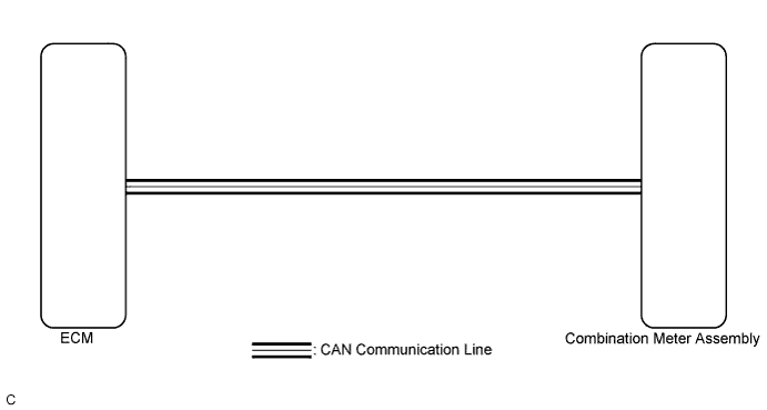
In this circuit, the meter ECU receives engine coolant temperature signals from the ECM using the CAN communication system. The meter ECU displays engine coolant temperature that is calculated based on the data received from the ECM.
WIRING DIAGRAM
INSPECTION PROCEDURE
Tech Tips
If there is an open or short in the engine coolant temperature sensor circuit, the ECM stores the DTCs. Troubleshoot the SFI System Click here for 2AR-FE, Click here for 2GR-FE).
PROCEDURE
-
CHECK CAN COMMUNICATION SYSTEM
-
Check if a CAN communication DTC is output Click here.
Result Result Proceed to CAN communication DTC is not output. A CAN communication DTC is output. B
B 
GO TO CAN COMMUNICATION SYSTEM Click here
A 
-
-
PERFORM ACTIVE TEST USING TECHSTREAM (WATER TEMPERATURE METER OPERATION)
-
Connect the Techstream to the DLC3.
-
Turn the ignition switch to ON.
-
Turn the Techstream on.
-
Enter the following menus: Body Electrical / Combination Meter / Active Test.
-
Check the operation by referring to the table below.
Combination Meter Tester Display Test Part Control Range Diagnostic Note Water Temperature Meter Operation Engine coolant temperature receiver gauge Low, Normal, High - OK Engine coolant temperature receiver gauge indication is normal.
NG
REPLACE COMBINATION METER ASSEMBLY Click here
OK
-
-
CHECK SFI SYSTEM
-
Check if the SFI system output the DTC Click here for 2AR-FE, Click here for 2GR-FE).
Result Result Proceed to The DTC is not output. A The DTC is output (for 2AR-FE). B The DTC is output (for 2GR-FE). C
B
GO TO SFI SYSTEM Click here
C
GO TO SFI SYSTEM Click here
A
-
-
READ VALUE USING TECHSTREAM (COOLANT TEMPERATURE, COOLANT TEMP)
-
Connect the Techstream to the DLC3.
-
Turn the ignition switch to ON.
-
Turn the Techstream on.
-
Enter the following menus:
-
for Combination Meter: Body Electrical / Combination Meter / Data List.
-
for Engine and ECT: Powertrain / Engine and ECT / Data List.
-
-
Check the values by referring to the table below.
Combination Meter Tester Display Measurement Item/Range Normal Condition Diagnostic Note Coolant Temperature Engine coolant temperature/-40 to 140°C (-40 to 284°F) After warming up: 75 to 100°C (167 to 212°F)
-
If -40°C (-40°F): Sensor circuit open
-
If 140°C (284°F) or more: Sensor circuit shorted
Engine and ECT Tester Display Measurement Item/Range Normal Condition Diagnostic Note Coolant Temp Coolant temperature/Min.: -40°C (-40°F), Max.: 140°C (284°F) 75 to 100°C (167 to 212°F): After warming up
-
Stored as Freeze Frame Data
-
This is the engine coolant temperature.
Tech Tips
-
After warming up the engine, the engine coolant temperature is 75 to 100°C (167 to 212°F).
-
After a long soak, the engine coolant temperature, intake air temperature and ambient air temperature are approximately equal.
-
If the value is -40°C (-40°F), or higher than 135°C (275°F), the sensor circuit is open or shorted.
-
Check if the engine overheats when the value indicates higher than 135°C (275°F).
Result Result Proceed to The Data List values of the ECUs match. A The Data List values of the ECUs do not match (for 2AR-FE). B The Data List values of the ECUs do not match (for 2GR-FE). C Tech Tips
-
When the Data List values of the ECUs match, an internal malfunction of the combination meter assembly is suspected.
-
When the Data List values of the ECUs do not match, a signal output error of the ECM or an internal malfunction of the combination meter assembly is suspected
-
B
REPLACE ECM Click here
C
REPLACE ECM Click here
A 
REPLACE COMBINATION METER ASSEMBLY Click here
-