REMOTE ENGINE STARTER SYSTEM Remote Engine Starter does not Operate
DESCRIPTION
When the remote engine starter ECU receives wireless signals via BERKES and CAN communication line, the remote engine starter ECU transmits the signals to each ECU through the main body ECU (multiplex network body ECU) via the CAN communication line, and starts or stops the engine.
Tech Tips
If all of the following conditions are met, the engine starts using the remote engine start function:
-
The shift lever is in P.
-
All doors are closed.
-
All doors are locked.
-
The engine hood is closed.
-
The engine switch is off.
-
The engine switch is not pressed.
-
The engine speed is not input.
-
Vehicle speed is not input.
-
Brake pedal is not depressed.
-
The theft deterrent system is not alarm sounding state.
The engine will stop when any of the following conditions is met:
-
10 minutes elapse after the engine is started.
-
The shift lever is moved from P.
-
Any door is opened.
-
Any door is unlocked.
-
The engine hood is opened.
-
The engine switch is turned on (ACC or IG).
-
The engine speed is kept less than 200 rpm for 40 seconds.
-
The engine speed is kept more than 3000 rpm for 3 seconds.
-
Vehicle speed is input (more than 5 km/h (3 mph)).
-
Brake pedal is depressed.
-
The theft deterrent system is alarm sounding state.
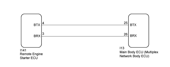
WIRING DIAGRAM
INSPECTION PROCEDURE
Note
Before replacing the remote engine starter ECU, refer to Registration Click here.
PROCEDURE
-
CHECK REMOTE ENGINE STARTER SYSTEM
-
Check the remote engine starter function Click here.
Result Result Proceed to Engine does not start using remote engine start function A Engine does not stop using remote engine stop function B
B 
CHECK ENGINE STOP FUNCTION Click here
A 
-
-
CHECK DTC OUTPUT (CAN COMMUNICATION SYSTEM)
-
Check if CAN communication DTCs are output Click here.
Tech Tips
If any DTCs for CAN communication are output, inspect those DTCs first.
OK CAN communication DTC is not output.
NG 
GO TO CAN COMMUNICATION SYSTEM Click here
OK
-
-
CHECK DTC OUTPUT (HEALTH CHECK)
-
Connect the Techstream to the DLC3.
-
Turn the engine switch on (IG).
-
Enter the following menus: System Select / Health Check.
Tech Tips
If any DTCs are output, inspect those DTCs first.
Result Result Proceed to DTCs are not output A DTCs are output B
B
GO TO DIAGNOSTIC TROUBLE CODE CHART
A
-
-
CHECK DIAGNOSTIC FACTOR INDICATION
-
Enter diagnostic mode Click here.
-
Check the engine stop factor.
OK Hazard warning lights do not flash (No abnormal stop in the past).
NG
CHECK ENGINE STOP FACTOR (HAZARD WARNING LIGHT FLASHING PATTERN) Click here
OK 
USE SIMULATION METHOD TO CHECK Click here
-
-
CHECK ENGINE STOP FACTOR (HAZARD WARNING LIGHT FLASHING PATTERN)
-
Check the engine stop factor.
Result Result Proceed to Hazard warning lights flash 3 times (Engine speed is too high or low) [for 2GR-FE] A Hazard warning lights flash 3 times (Engine speed is too high or low) [for 2AR-FE] B Hazard warning lights flash 7 or 8 times (Brake pedal is pushed or vehicle speed is abnormal) C Hazard warning lights flash 9 times (Immobiliser collation discrepancy) D Except above (Other engine stop factor) E
B
GO TO SFI SYSTEM Click here
C
GO TO VEHICLE STABILITY CONTROL SYSTEM Click here
D
GO TO ENGINE IMMOBILISER SYSTEM Click here
E
CONFIRM OTHER ENGINE STOP FACTOR Click here
A
GO TO SFI SYSTEM Click here
-
-
CONFIRM OTHER ENGINE STOP FACTOR
-
Confirm the engine stop factor and the vehicle condition.
Tech Tips
-
Possible other engine stop factor is listed below.
-
Hazard warning lights are flashed 1 time (engine switch on (ACC or IG))
-
Hazard warning lights are flashed 2 times (any door is unlocked)
-
Hazard warning lights are flashed 5 times (Any door or engine hood is opened)
-
Hazard warning lights are flashed 6 times (Shift lever is not in P)
OK Vehicle condition differs from the engine stop factor. -
NG
CORRECT VEHICLE CONDITION (OTHER ENGINE STOP FACTOR)
OK
-
-
CHECK ENGINE START FUNCTION (FUEL LEVEL REMAINS IN THE TANK)
-
Check that the fuel remaining in the tank is enough to start the engine or not.
OK Engine starts with the engine switch operation.
NG
ADD FUEL
OK
-
-
CHECK CRANKING FUNCTION (REMOTE ENGINE START FUNCTION)
-
Perform the remote engine start operation Click here.
-
Check if the engine cranks using the remote engine start function.
Result Result Proceed to Engine cranks A Engine does not crank B
B
CHECK REMOTE ENGINE STARTER ECU (OUTPUT SIGNAL) Click here
A
-
-
CHECK WIRELESS DOOR LOCK CONTROL SYSTEM
-
Check the wireless door lock control functions using the electrical key transmitter sub-assembly Click here.
OK Wireless door lock/unlock operates normally.
NG
GO TO WIRELESS DOOR LOCK CONTROL SYSTEM Click here
OK
-
-
CHECK HARNESS AND CONNECTOR (MAIN BODY ECU (MULTIPLEX NETWORK BODY ECU) - REMOTE ENGINE STARTER ECU)
-
Disconnect the I13 main body ECU (multiplex network body ECU) connector.
-
Disconnect the I141 remote engine starter ECU connector.
-
Measure the resistance according to the value(s) in the below.
Standard Resistance Tester Connection Condition Specified condition I13-25 (BTX) - I141-4 (BTX) Always Below 1 Ω I13-26 (BRX) - I141-3 (BRX) Always Below 1 Ω I13-25 (BTX) - Body ground Always 10 KΩ or higher I13-26 (BRX) - Body ground Always 10 KΩ or higher
NG
REPAIR OR REPLACE HARNESS OR CONNECTOR
OK
-
-
CHECK REMOTE ENGINE STARTER ECU (OUTPUT SIGNAL)
-
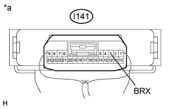
Text in Illustration *a Component with harness connected
(Remote Engine Starter ECU)
Reconnect the I141 remote engine starter ECU connector.
-
Using an oscilloscope, check the waveform.
Waveform (Reference) Item Content Tester Connection I141-3 (BRX) - Body ground Tool Setting 5 V/DIV., 20 ms./DIV. Condition Remote engine start function is operated OK The remote engine starter ECU outputs a waveform within 20 seconds after the remote engine start function is activated.
NG
REPLACE REMOTE ENGINE STARTER ECU Click here
OK
REPLACE MAIN BODY ECU (MULTIPLEX NETWORK BODY ECU) Click here
-
-
CHECK ENGINE STOP FUNCTION
-
Check if the engine stops when any of the following conditions is met.
-
10 minutes elapse after the engine is started.
-
The shift lever is moved from P.
-
Any door is opened.
-
Any door is unlocked.
-
The engine hood is opened.
-
The engine switch is turned on (ACC or IG).
-
The engine speed is kept less than 200 rpm for 40 seconds.
-
The engine speed is kept more than 3000 rpm for 3 seconds.
-
Vehicle speed is input (more than 5 km/h (3 mph)).
-
Brake pedal is depressed.
-
The theft deterrent system is alarm sounding state.
OK The engine stops. -
NG
REPLACE REMOTE ENGINE STARTER ECU Click here
OK
-
-
CHECK WIRELESS DOOR LOCK CONTROL SYSTEM
-
Check the wireless door lock control functions using the electrical key transmitter sub-assembly Click here.
OK Wireless door lock/unlock operates normally.
NG
GO TO WIRELESS DOOR LOCK CONTROL SYSTEM Click here
OK
REPLACE REMOTE ENGINE STARTER ECU Click here
-