SAFETY CONNECT SYSTEM, Diagnostic DTC:B15C5

| DTC Code | DTC Name |
|---|---|
| B15C5 | Manual Button Malfunction |
DESCRIPTION
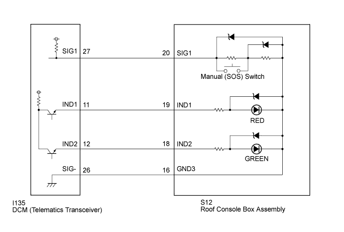
This DTC is set when the DCM (Telematics Transceiver) detects an open or short circuit in the manual (SOS) switch.
| DTC No. | DTC Detection Condition | Trouble Area |
|---|---|---|
| B15C5 | Open or short circuit in manual (SOS) switch is detected. |
|
WIRING DIAGRAM
INSPECTION PROCEDURE
PROCEDURE
-
CHECK DTC
-
Turn the engine switch off.
-
Connect the Techstream to the DLC3.
-
Turn the engine switch on (IG) and wait for 10 seconds.
-
Turn the Techstream on.
-
Perform "Health Check" and check for current DTCs Click here.
Result Result Proceed to DTC B1570, B1571 and B15C5 are output A DTC B15C5 is output
(DTC B1570 and B1571 are not output)
B
B 
READ VALUE USING TECHSTREAM (MANUAL (SOS) SWITCH OPERATION) Click here
A 
-
-
INSPECT ROOF CONSOLE BOX ASSEMBLY (MANUAL (SOS) SWITCH)
-
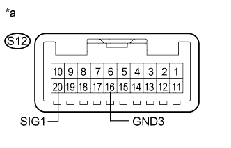
Text in Illustration *a Component without harness connected
(Roof Console Box Assembly)
Disconnect the S12 roof console box assembly connector.
-
Measure the resistance according to the value(s) in the table below.
Standard Resistance Tester Connection Condition Specified Condition S12-20 (SIG1) - S12-16 (GND3) Manual (SOS) switch not pressed 410 to 414 Ω S12-20 (SIG1) - S12-16 (GND3) Manual (SOS) switch pressed 81 to 83 Ω
NG 
REPLACE ROOF CONSOLE BOX ASSEMBLY Click here
OK
-
-
CHECK HARNESS AND CONNECTOR (DCM (TELEMATICS TRANSCEIVER) - ROOF CONSOLE BOX ASSEMBLY)
-
Disconnect the I135 DCM (Telematics Transceiver) connector.
-
Disconnect the S12 roof console box assembly connector.
-
Measure the resistance according to the value(s) in the table below.
Standard Resistance Tester Connection Condition Specified Condition I135-26 (SIG-) - S12-16 (GND3) Always Below 1 Ω I135-26 (SIG-) - Body ground Always 10 kΩ or higher
NG
REPAIR OR REPLACE HARNESS OR CONNECTOR
OK
-
-
REPLACE DCM (TELEMATICS TRANSCEIVER)
-
Replace the DCM (Telematics Transceiver) Click here.
Note
-
The engine switch must be off.
-
Do not swap the DCM (Telematics Transceiver) with one from another vehicle.
-
NEXT 
PERFORM DCM ACTIVATION Click here
-
-
READ VALUE USING TECHSTREAM (MANUAL (SOS) SWITCH OPERATION)
-
Turn the engine switch off.
-
Connect the Techstream to the DLC3.
-
Turn the engine switch on (IG) and wait for 10 seconds.
-
Turn the Techstream on.
-
Enter the following menus: Body Electrical / Telematics / Data List.
-
Check that the manual (SOS) switch condition observed on the Techstream changes according to manual (SOS) switch operation.
Telematics Tester Display Measurement Item/Range Normal Condition Diagnostic Note Emergency Switch Manual (SOS) switch / OFF or ON OFF: Manual (SOS) switch not pressed - ON: Manual (SOS) switch pressed* -
-
*: Pressing the manual (SOS) switch will connect to the call center.
Result Result Proceed to Techstream display changes when turning the manual (SOS) switch ON/OFF. A Techstream display does not change when turning the manual (SOS) switch ON/OFF. B -
B
INSPECT DCM (TELEMATICS TRANSCEIVER) (SIG1 VOLTAGE) Click here
A
-
-
REPLACE DCM (TELEMATICS TRANSCEIVER)
-
Replace the DCM (Telematics Transceiver) Click here.
Note
-
The engine switch must be off.
-
Do not swap the DCM (Telematics Transceiver) with one from another vehicle.
-
NEXT
PERFORM DCM ACTIVATION Click here
-
-
INSPECT DCM (TELEMATICS TRANSCEIVER) (SIG1 VOLTAGE)
-
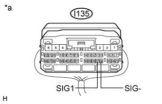
Text in Illustration *a Component with harness connected
(DCM (Telematics Transceiver))
Remove the DCM (Telematics Transceiver) but do not disconnect the connectors Click here.
-
Measure the voltage according to the value(s) in the table below.
Standard Voltage Tester Connection Condition Specified Condition I135-27 (SIG1) - I135-26 (SIG-) Engine switch on (IG), manual (SOS) switch not pressed 1.5 to 2.0 V
NG
INSPECT ROOF CONSOLE BOX ASSEMBLY (MANUAL (SOS) SWITCH) Click here
OK
-
-
REPLACE DCM (TELEMATICS TRANSCEIVER)
-
Replace the DCM (Telematics Transceiver) Click here.
Note
-
The engine switch must be off.
-
Do not swap the DCM (Telematics Transceiver) with one from another vehicle.
-
NEXT
PERFORM DCM ACTIVATION Click here
-
-
INSPECT ROOF CONSOLE BOX ASSEMBLY (MANUAL (SOS) SWITCH)
-
Text in Illustration *a Component without harness connected
(Roof Console Box Assembly)
Disconnect the S12 roof console box assembly connector.
-
Measure the resistance according to the value(s) in the table below.
Standard Resistance Tester Connection Condition Specified Condition S12-20 (SIG1) - S12-16 (GND3) Manual (SOS) switch not pressed 410 to 414 Ω S12-20 (SIG1) - S12-16 (GND3) Manual (SOS) switch pressed 81 to 83 Ω
NG
REPLACE ROOF CONSOLE BOX ASSEMBLY Click here
OK
-
-
CHECK HARNESS AND CONNECTOR (DCM (TELEMATICS TRANSCEIVER) - ROOF CONSOLE BOX ASSEMBLY)
-
Disconnect the I135 DCM (Telematics Transceiver) connector.
-
Disconnect the S12 roof console box assembly connector.
-
Measure the resistance according to the value(s) in the table below.
Standard Resistance Tester Connection Condition Specified Condition I135-27 (SIG1) - S12-20 (SIG1) Always Below 1 Ω I135-27 (SIG1) - Body ground Always 10 kΩ or higher
NG
REPAIR OR REPLACE HARNESS OR CONNECTOR
OK
-
-
REPLACE DCM (TELEMATICS TRANSCEIVER)
-
Replace the DCM (Telematics Transceiver) Click here.
Note
-
The engine switch must be off.
-
Do not swap the DCM (Telematics Transceiver) with one from another vehicle.
-
NEXT
PERFORM DCM ACTIVATION Click here
-