SAFETY CONNECT SYSTEM, Diagnostic DTC:B1573, B15CB

| DTC Code | DTC Name |
|---|---|
| B1573 | Short in Telephone Antenna Circuit |
| B15CB | Telematics Transceiver Antenna Disconnected |
DESCRIPTION
This DTC is set when the DCM (Telematics Transceiver) detects an open or a short in the telephone and GPS antenna circuit. The DCM (Telematics Transceiver) oscillates and receives 824 - 894 MHz or 1850 - 1990 MHz radio-frequency through the telephone and GPS antenna assembly.
| DTC No. | DTC Detection Condition | Trouble Area |
|---|---|---|
| B1573 | Telephone and GPS antenna assembly impedance is lower than malfunction criterion for 10 seconds when engine switch is on (IG). (Short circuit) |
|
| B15CB | Telephone and GPS antenna assembly impedance is higher than malfunction criterion for 10 seconds when engine switch is on (IG). (Open circuit) |
Tech Tips
Refer to "PARTS LOCATION" for the installation location of telephone and GPS antenna cord Click here.
INSPECTION PROCEDURE
PROCEDURE
-
CHECK DTC
-
Turn the engine switch off.
-
Connect the Techstream to the DLC3.
-
Turn the engine switch on (IG) and wait for 10 seconds.
-
Turn the Techstream on.
-
Perform "HEALTH CHECK" and check for current DTCs Click here.
Result Result Proceed to DTC B1573 or B15CB is output A DTC B1573 or B15CB is not output B
B 
CHECK FOR INTERMITTENT PROBLEMS Click here
A 
-
-
INSPECT TELEPHONE AND GPS ANTENNA ASSEMBLY
-
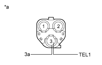
Text in Illustration *a Telephone and GPS Antenna Assembly Disconnect the telephone and GPS antenna assembly connector from the telephone and GPS antenna cord (No. 2 floor wire).
-
Measure the resistance according to the value(s) in the table below.
Standard Resistance Tester Connection Condition Specified Condition 3 (TEL1) - 3a Always 4 to 11 kΩ
NG
REPLACE TELEPHONE AND GPS ANTENNA ASSEMBLY Click here
OK
-
-
INSPECT TELEPHONE AND GPS ANTENNA CORD (NO. 2 FLOOR WIRE)
-
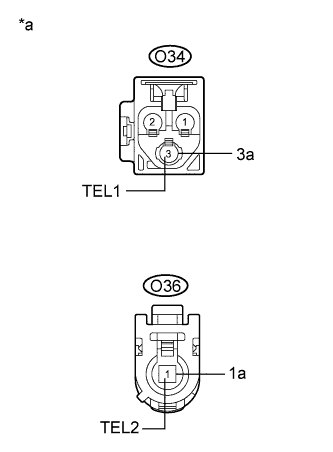
Text in Illustration *a Telephone and GPS antenna cord (No. 2 Floor Wire) Disconnect the telephone and GPS antenna cord (No. 2 floor wire) connector from the DCM (Telematics Transceiver).
-
Measure the resistance according to the value(s) in the table below.
Standard Resistance Tester Connection Condition Specified Condition O34-3 (TEL1) - O36-1 (TEL2) Always Below 1 Ω O34-3a - O36-1a Always Below 1 Ω O34-3 (TEL1) - Body ground Always 10 kΩ or higher O34-3a - Body ground Always 10 kΩ or higher
NG
REPLACE TELEPHONE AND GPS ANTENNA CORD (NO. 2 FLOOR WIRE)
OK
-
-
REPLACE TELEPHONE AND GPS ANTENNA ASSEMBLY
-
Replace the telephone and GPS antenna assembly with a known good one and check if the same problem occurs again Click here.
OK The system returns to normal.
NG 
REPLACE DCM (TELEMATICS TRANSCEIVER) Click here
OK 
END
-
-
REPLACE DCM (TELEMATICS TRANSCEIVER)
-
Replace the DCM (Telematics Transceiver) Click here.
Note
-
The engine switch must be off.
-
Do not swap the DCM (Telematics Transceiver) with one from another vehicle.
-
NEXT
PERFORM DCM ACTIVATION Click here
-