SAFETY CONNECT SYSTEM, Diagnostic DTC:B1572

| DTC Code | DTC Name |
|---|---|
| B1572 | Telephone Microphone Error |
DESCRIPTION
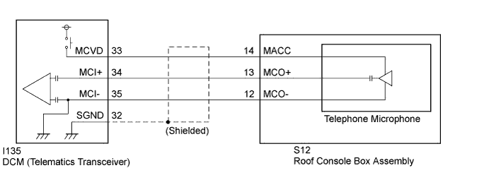
This DTC is set when the DCM (Telematics Transceiver) detects a malfunction in the telephone microphone circuit.
| DTC No. | DTC Detection Condition | Trouble Area |
|---|---|---|
| B1572 | Current of MCVD reaches malfunction criteria for 10 seconds while engine switch is on (IG). |
|
WIRING DIAGRAM
INSPECTION PROCEDURE
PROCEDURE
-
CHECK DTC
-
Turn the engine switch off.
-
Connect the Techstream to the DLC3.
-
Turn the engine switch on (IG) and wait for 10 seconds.
-
Turn the Techstream on.
-
Perform "Health Check" and check for current DTCs Click here.
Result Result Proceed to DTC B1572 is output A DTC B1572 is not output B
B 
CHECK FOR INTERMITTENT PROBLEMS Click here
A 
-
-
INSPECT ROOF CONSOLE BOX ASSEMBLY (TELEPHONE MICROPHONE POWER SOURCE)
-
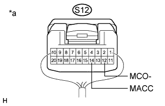
Text in Illustration *a Component with harness connected
(Roof Console Box Assembly)
Remove the roof console box assembly but do not disconnect the connectors Click here.
-
Measure the voltage and resistance according to the value(s) in the table below.
Standard Voltage Tester Connection Condition Specified Condition S12-14 (MACC) - Body ground Engine switch on (ACC) 4 to 6 V Standard Resistance Tester Connection Condition Specified Condition S12-12 (MCO-) - Body ground Always Below 1 Ω
NG 
INSPECT DCM (TELEMATICS TRANSCEIVER) (TELEPHONE MICROPHONE POWER SOURCE) Click here
OK
-
-
CHECK HARNESS AND CONNECTOR (DCM (TELEMATICS TRANSCEIVER) - ROOF CONSOLE BOX ASSEMBLY)
-
Disconnect the I135 DCM (Telematics Transceiver) connector.
-
Disconnect the S12 roof console box assembly connector.
-
Measure the resistance according to the value(s) in the table below.
Standard Resistance Tester Connection Condition Specified Condition I135-34 (MCI+) - S12-13 (MCO+) Always Below 1 Ω I135-35 (MCI-) - S12-12 (MCO-) Always Below 1 Ω I135-34 (MCI+) - Body ground Always 10 kΩ or higher I135-35 (MCI-) - Body ground Always 10 kΩ or higher I135-32 (SGND) - Body ground Always 10 kΩ or higher
NG
REPAIR OR REPLACE HARNESS OR CONNECTOR
OK 
REPLACE TELEPHONE MICROPHONE (ROOF CONSOLE BOX ASSEMBLY) Click here
-
-
INSPECT DCM (TELEMATICS TRANSCEIVER) (TELEPHONE MICROPHONE POWER SOURCE)
-
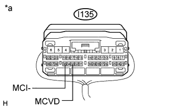
Text in Illustration *a Component with harness connected
(DCM (Telematics Transceiver))
Remove the DCM (Telematics Transceiver) but do not disconnect the connectors Click here.
-
Measure the voltage and resistance according to the value(s) in the table below.
Standard Voltage Tester Connection Condition Specified Condition I135-33 (MCVD) - Body ground Engine switch on (ACC) 4 to 6 V Standard Resistance Tester Connection Condition Specified Condition I135-35 (MCI-) - Body ground Always Below 1 Ω
NG
REPLACE DCM (TELEMATICS TRANSCEIVER) Click here
OK
REPAIR OR REPLACE HARNESS OR CONNECTOR
-
-
REPLACE DCM (TELEMATICS TRANSCEIVER)
-
Replace the DCM (Telematics Transceiver) Click here.
Note
-
The engine switch must be off.
-
Do not swap the DCM (Telematics Transceiver) with one from another vehicle.
-
NEXT
PERFORM DCM ACTIVATION Click here
-