NAVIGATION SYSTEM (for Navigation Receiver Type) Speaker Circuit
DESCRIPTION
-
If there is a short in a speaker circuit, the stereo component amplifier assembly detects it and stops output to the speakers.
-
Thus sound cannot be heard from the speakers even if there is no malfunction in the stereo component amplifier assembly, DCM (telematics transceiver)*1 or speakers.
-
If a short is detected in a speaker circuit, no sound can be heard from the speakers.
-
*1: w/ Manual (SOS) Switch
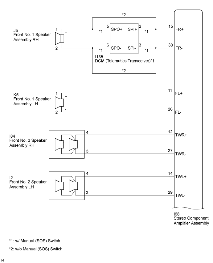
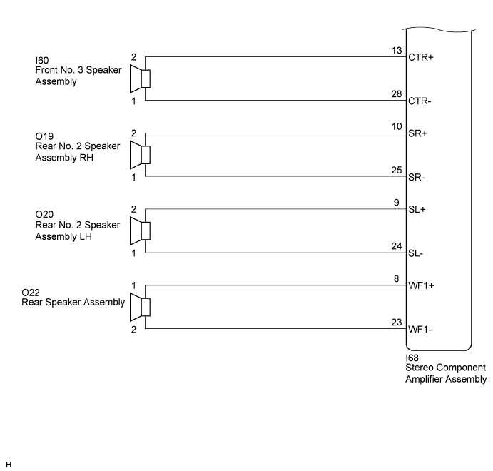
WIRING DIAGRAM
INSPECTION PROCEDURE
PROCEDURE
-
CHECK HARNESS AND CONNECTOR
-
Disconnect the connectors from the stereo component amplifier assembly, DCM (telematics transceiver)*1 and speakers.
-
*1: w/ Manual (SOS) Switch
-
-
w/ Manual (SOS) Switch
Measure the resistance between the stereo component amplifier assembly and the DCM (telematics transceiver) to check for an open circuit in the wire harness.
Standard Resistance Tester Connection Condition Specified Condition I68-15 (FR+) - I135-2 (SPI+) Always Below 1 Ω I68-30 (FR-) - I135-3 (SPI-) Always Below 1 Ω -
w/ Manual (SOS) Switch
Measure the resistance between the front No. 1 speaker assembly RH and the DCM (telematics transceiver) to check for an open circuit in the wire harness.
Standard Resistance Tester Connection Condition Specified Condition J5-1 (+) - I135-5 (SPO+) Always Below 1 Ω J5-2 (-) - I135-6 (SPO-) Always Below 1 Ω -
w/o Manual (SOS) Switch
Measure the resistance between the front No. 1 speaker assembly RH and the stereo component amplifier assembly to check for an open circuit in the wire harness.
Standard Resistance Tester Connection Condition Specified Condition I68-15 (FR+) - J5-1 (+) Always Below 1 Ω I68-30 (FR-) - J5-2 (-) Always Below 1 Ω -
Measure the resistance between the front No. 1 speaker assembly LH and the stereo component amplifier assembly to check for an open circuit in the wire harness.
Standard Resistance Tester Connection Condition Specified Condition I68-11 (FL+) - K5-1 (+) Always Below 1 Ω I68-26 (FL-) - K5-2 (-) Always Below 1 Ω -
Measure the resistance between each of the front No. 2 speaker assemblies and the stereo component amplifier assembly to check for an open circuit in the wire harness.
Standard Resistance Tester Connection Condition Specified Condition I68-12 (TWR+) - I84-4 Always Below 1 Ω I68-27 (TWR-) - I84-3 Always Below 1 Ω I68-14 (TWL+) - I2-4 Always Below 1 Ω I68-29 (TWL-) - I2-3 Always Below 1 Ω -
Measure the resistance between the front No. 3 speaker assembly and the stereo component amplifier assembly to check for an open circuit in the wire harness.
Standard Resistance Tester Connection Condition Specified Condition I68-13 (CTR+) - I60-2 Always Below 1 Ω I68-28 (CTR-) - I60-1 Always Below 1 Ω -
Measure the resistance between each of the rear No. 2 speaker assemblies and the stereo component amplifier assembly to check for an open circuit in the wire harness.
Standard Resistance Tester Connection Condition Specified Condition I68-10 (SR+) - O19-2 Always Below 1 Ω I68-25 (SR-) - O19-1 Always Below 1 Ω I68-9 (SL+) - O20-2 Always Below 1 Ω I68-24 (SL-) - O20-1 Always Below 1 Ω -
Measure the resistance between the rear speaker assembly and the stereo component amplifier assembly to check for an open circuit in the wire harness.
Standard Resistance Tester Connection Condition Specified Condition I68-8 (WF1+) - O22-1 Always Below 1 Ω I68-23 (WF1-) - O22-2 Always Below 1 Ω -
Measure the resistance between the stereo component amplifier assembly and body ground to check for a short circuit in the wire harness.
Standard Resistance Tester Connection Condition Specified Condition I68-15 (FR+) - Body ground Always 10 kΩ or higher I68-30 (FR-) - Body ground Always 10 kΩ or higher I68-11 (FL+) - Body ground Always 10 kΩ or higher I68-26 (FL-) - Body ground Always 10 kΩ or higher I68-12 (TWR+) - Body ground Always 10 kΩ or higher I68-27 (TWR-) - Body ground Always 10 kΩ or higher I68-14 (TWL+) - Body ground Always 10 kΩ or higher I68-29 (TWL-) - Body ground Always 10 kΩ or higher I68-13 (CTR+) - Body ground Always 10 kΩ or higher I68-28 (CTR-) - Body ground Always 10 kΩ or higher I68-10 (SR+) - Body ground Always 10 kΩ or higher I68-25 (SR-) - Body ground Always 10 kΩ or higher I68-9 (SL+) - Body ground Always 10 kΩ or higher I68-24 (SL-) - Body ground Always 10 kΩ or higher I68-8 (WF1+) - Body ground Always 10 kΩ or higher I68-23 (WF1-) - Body ground Always 10 kΩ or higher -
w/ Manual (SOS) Switch
Measure the resistance between the DCM (telematics transceiver) and body ground to check for a short circuit in the wire harness.
Standard Resistance Tester Connection Condition Specified Condition I135-5 (SPO+) - Body ground Always 10 kΩ or higher I135-6 (SPO-) - Body ground Always 10 kΩ or higher
NG 
REPAIR OR REPLACE HARNESS OR CONNECTOR
OK 
-
-
INSPECT FRONT NO. 1 SPEAKER ASSEMBLY
-
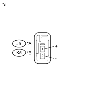
Text in Illustration *A for RH *B for LH *a Component without harness connected
(Front No. 1 Speaker Assembly)
Resistance check
-
Measure the resistance according to the value(s) in the table below.
Standard Resistance Tester Connection Condition Specified Condition J5-1 (+) - J5-2 (-) Always 4.6 to 6.6 Ω K5-1 (+) - K5-2 (-) Always 4.6 to 6.6 Ω
-
NG
REPLACE FRONT NO. 1 SPEAKER ASSEMBLY Click here
OK
-
-
INSPECT FRONT NO. 2 SPEAKER ASSEMBLY
-
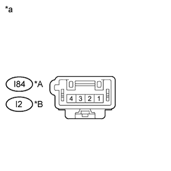
Text in Illustration *A for RH *B for LH *a Component without harness connected
(Front No. 2 Speaker Assembly)
Resistance check
-
Measure the resistance according to the value(s) in the table below.
Standard Resistance Tester Connection Condition Specified Condition I84-4 - I84-3 Always 3.4 to 5.2 Ω I2-4 - I2-3 Always 3.4 to 5.2 Ω
-
NG
REPLACE FRONT NO. 2 SPEAKER ASSEMBLY Click here
OK
-
-
INSPECT FRONT NO. 3 SPEAKER ASSEMBLY
-
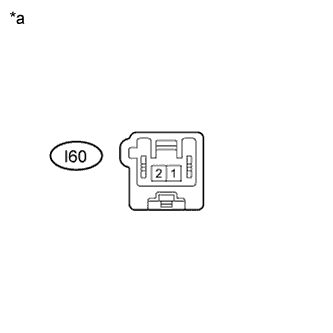
Text in Illustration *a Component without harness connected
(Front No. 3 Speaker Assembly)
Resistance check
-
Measure the resistance according to the value(s) in the table below.
Standard Resistance Tester Connection Condition Specified Condition I60-1 - I60-2 Always 6.8 to 10.2 Ω
-
NG
REPLACE FRONT NO. 3 SPEAKER ASSEMBLY Click here
OK
-
-
INSPECT REAR NO. 2 SPEAKER ASSEMBLY
-
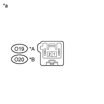
Text in Illustration *A for RH *B for LH *a Component without harness connected
(Rear No. 2 Speaker Assembly)
Resistance check
-
Measure the resistance according to the value(s) in the table below.
Standard Resistance Tester Connection Condition Specified Condition O19-1 - O19-2 Always 6.8 to 10.2 Ω O20-1 - O20-2 Always 6.8 to 10.2 Ω
-
NG
REPLACE REAR NO. 2 SPEAKER ASSEMBLY Click here
OK
-
-
INSPECT REAR SPEAKER ASSEMBLY
-
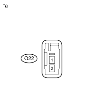
Text in Illustration *a Component without harness connected
(Rear Speaker Assembly)
Resistance check
-
Measure the resistance according to the value(s) in the table below.
Standard Resistance Tester Connection Condition Specified Condition O22-1 - O22-2 Always 4.8 to 6.8 Ω
-
-
Proceed to the next step based on the inspection result.
Result Condition Proceed to OK (w/ Manual (SOS) Switch) A OK (w/o Manual (SOS) Switch) B NG C
B
PROCEED TO NEXT SUSPECTED AREA SHOWN IN PROBLEM SYMPTOMS TABLE Click here
C
REPLACE REAR SPEAKER ASSEMBLY Click here
A
-
-
INSPECT DCM (TELEMATICS TRANSCEIVER)
-
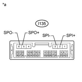
Text in Illustration *a Component without harness connected
(DCM (Telematics Transceiver))
Resistance check
-
Measure the resistance according to the value(s) in the table below.
Standard Resistance Tester Connection Condition Specified Condition I135-2 (SPI+) - I135-5 (SPO+) Always Below 1 Ω I135-3 (SPI-) - I135-6 (SPO-) Always Below 1 Ω I135-2 (SPI+) - I135-3 (SPI-) Always 10 kΩ or higher I135-5 (SPO+) - I135-6 (SPO-) Always 10 kΩ or higher I135-2 (SPI+) - Body ground Always 10 kΩ or higher I135-3 (SPI-) - Body ground Always 10 kΩ or higher
-
NG
REPLACE DCM (TELEMATICS TRANSCEIVER) Click here
OK 
PROCEED TO NEXT SUSPECTED AREA SHOWN IN PROBLEM SYMPTOMS TABLE Click here
-