NAVIGATION SYSTEM (for Radio and Display Type) Reverse Signal Circuit
DESCRIPTION
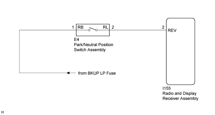
The radio and display receiver assembly receives a reverse signal from the park/neutral position switch assembly to use for adjusting the vehicle position on the multi-display.
WIRING DIAGRAM
INSPECTION PROCEDURE
PROCEDURE
-
CHECK HARNESS AND CONNECTOR (REVERSE SIGNAL)
-
Disconnect the radio and display receiver assembly connector.
-
Measure the voltage according to the value(s) in the table below.
Standard Voltage Tester Connection Condition Specified Condition I155-2 (REV) - Body ground Ignition switch ON
Shift lever in R
11 to 14 V I155-2 (REV) - Body ground Ignition switch ON
Shift lever in any position other than R
Below 1 V
NG 
CHECK HARNESS AND CONNECTOR (RADIO AND DISPLAY RECEIVER ASSEMBLY - PARK/NEUTRAL POSITION SWITCH ASSEMBLY) Click here
OK 
PROCEED TO NEXT SUSPECTED AREA SHOWN IN PROBLEM SYMPTOMS TABLE Click here
-
-
CHECK HARNESS AND CONNECTOR (RADIO AND DISPLAY RECEIVER ASSEMBLY - PARK/NEUTRAL POSITION SWITCH ASSEMBLY)
-
Disconnect the radio and display receiver assembly connector.
-
Disconnect the park/neutral position switch assembly connector.
-
Measure the resistance according to the value(s) in the table below.
Standard Resistance Tester Connection Condition Specified Condition I155-2 (REV) - E4-2 (RL) Always Below 1 Ω I155-2 (REV) - Body ground Always 10 kΩ or higher
NG 
REPAIR OR REPLACE HARNESS OR CONNECTOR
OK 
-
-
CHECK HARNESS AND CONNECTOR (PARK/NEUTRAL POSITION SWITCH ASSEMBLY - BATTERY)
-
Disconnect the park/neutral position switch assembly connector.
-
Measure the voltage according to the value(s) in the table below.
Standard Voltage Tester Connection Condition Specified Condition E4-1 (RB) - Body ground Ignition switch ON 11 to 14 V -
Proceed to the next step based on the check result.
Result Result Proceed to NG A OK (for U660E) B OK (for U760E) C
B
REPLACE PARK/NEUTRAL POSITION SWITCH ASSEMBLY (for U660E) Click here
C
REPLACE PARK/NEUTRAL POSITION SWITCH ASSEMBLY (for U760E) Click here
A
REPAIR OR REPLACE HARNESS OR CONNECTOR
-