NAVIGATION SYSTEM Navigation Voice Circuit
DESCRIPTION
This circuit is used when the voice switch of the steering pad switch assembly is pushed.
Using this circuit, the navigation receiver assembly sends signals to the stereo component amplifier assembly.
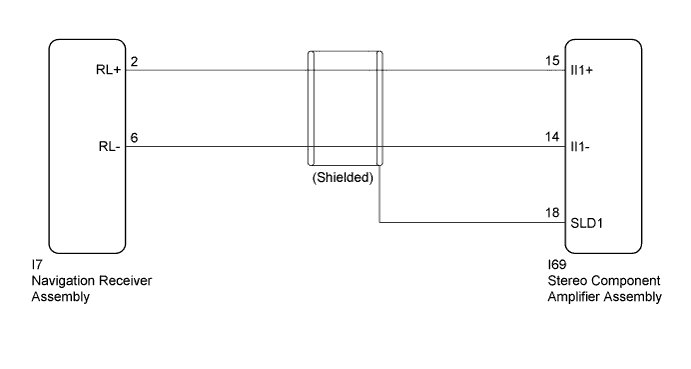
WIRING DIAGRAM
INSPECTION PROCEDURE
PROCEDURE
-
CHECK HARNESS AND CONNECTOR (NAVIGATION RECEIVER ASSEMBLY - STEREO COMPONENT AMPLIFIER ASSEMBLY)
-
Disconnect the I7 navigation receiver assembly connector.
-
Disconnect the I69 stereo component amplifier assembly connector.
-
Measure the resistance according to the value(s) in the table below.
Standard Resistance Tester connection Condition Specified condition I7-2 (RL+) - I69-15 (II1+) Always Below 1 Ω I7-6 (RL-) - I69-14 (II1-) Always Below 1 Ω I69-15 (II1+) - Body ground Always 10 kΩ or higher I69-14 (II1-) - Body ground Always 10 kΩ or higher I69-18 (SLD1) - Body ground Always 10 kΩ or higher
NG 
REPAIR OR REPLACE HARNESS OR CONNECTOR
OK 
PROCEED TO NEXT SUSPECTED AREA SHOWN IN PROBLEM SYMPTOMS TABLE Click here
-