AUDIO AND VISUAL SYSTEM (for Radio and Display Type with Intuitive Parking Assist System) Microphone Circuit between Microphone and Radio Receiver
DESCRIPTION
-
The navigation ECU sub-assembly and roof console box assembly (telephone microphone assembly) are connected to each other using the microphone connection detection signal lines.
-
Using this circuit, the navigation ECU sub-assembly sends power to the roof console box assembly (telephone microphone assembly), and the roof console box assembly (telephone microphone assembly) sends microphone signals to the navigation ECU sub-assembly.
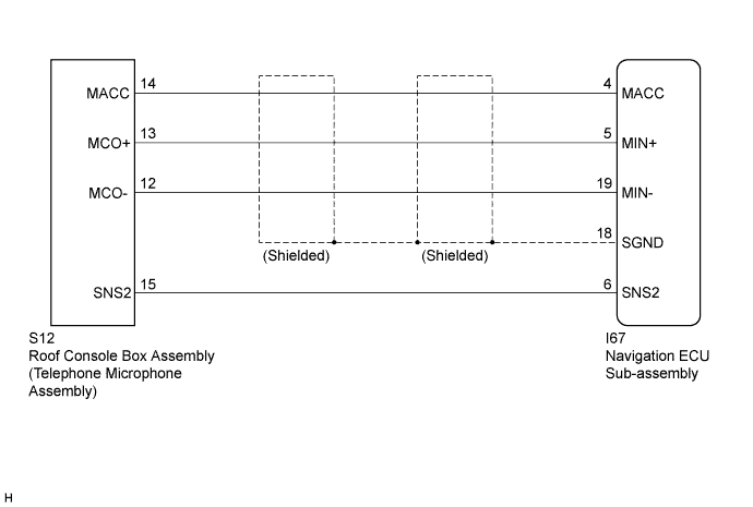
WIRING DIAGRAM
INSPECTION PROCEDURE
PROCEDURE
-
CHECK HARNESS AND CONNECTOR (NAVIGATION ECU SUB-ASSEMBLY - ROOF CONSOLE BOX ASSEMBLY (TELEPHONE MICROPHONE ASSEMBLY))
-
Disconnect the navigation ECU sub-assembly connector.
-
Disconnect the roof console box assembly (telephone microphone assembly) connector.
-
Measure the resistance according to the value(s) in the table below.
Standard Resistance Tester Connection Condition Specified Condition I67-4 (MACC) - S12-14 (MACC) Always Below 1 Ω I67-5 (MIN+) - S12-13 (MCO+) Always Below 1 Ω I67-19 (MIN-) - S12-12 (MCO-) Always Below 1 Ω I67-6 (SNS2) - S12-15 (SNS2) Always Below 1 Ω I67-4 (MACC) - Body ground Always 10 kΩ or higher I67-5 (MIN+) - Body ground Always 10 kΩ or higher I67-19 (MIN-) - Body ground Always 10 kΩ or higher I67-18 (SGND) - Body ground Always 10 kΩ or higher I67-6 (SNS2) - Body ground Always 10 kΩ or higher
NG 
REPAIR OR REPLACE HARNESS OR CONNECTOR
OK 
-
-
INSPECT NAVIGATION ECU SUB-ASSEMBLY
-
Reconnect the navigation ECU sub-assembly connector.
-
Reconnect the roof console box assembly (telephone microphone assembly) connector.
-
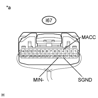
Text in Illustration *a Component with harness connected
(Navigation ECU Sub-assembly)
Measure the voltage according to the value(s) in the table below.
Standard Voltage Tester Connection Condition Specified Condition I67-4 (MACC) - Body ground Ignition switch ACC 4 to 6 V -
Measure the resistance according to the value(s) in the table below.
Standard Resistance Tester Connection Condition Specified Condition I67-18 (SGND) - Body ground Always Below 1 Ω I67-19 (MIN-) - Body ground Always Below 1 Ω
NG
REPLACE NAVIGATION ECU SUB-ASSEMBLY Click here
OK
-
-
INSPECT ROOF CONSOLE BOX ASSEMBLY (TELEPHONE MICROPHONE ASSEMBLY)
-
Disconnect the roof console box assembly (telephone microphone assembly) connector.
-
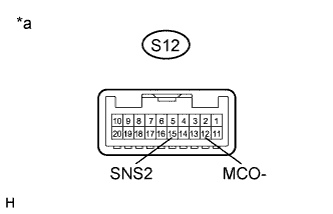
Text in Illustration *a Component without harness connected
(Roof Console Box Assembly (Telephone Microphone Assembly))
Measure the resistance according to the value(s) in the table below.
Standard Resistance Tester Connection Condition Specified Condition S12-15 (SNS2) - S12-12 (MCO-) Always Below 1 Ω
NG
REPLACE ROOF CONSOLE BOX ASSEMBLY (TELEPHONE MICROPHONE ASSEMBLY) Click here
OK
-
-
INSPECT ROOF CONSOLE BOX ASSEMBLY (TELEPHONE MICROPHONE ASSEMBLY)
-
Reconnect the navigation ECU sub-assembly connector.
-
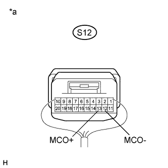
Text in Illustration *a Component with harness connected
(Roof Console Box Assembly (Telephone Microphone Assembly))
Reconnect the roof console box assembly (telephone microphone assembly) connector.
-
Turn the ignition switch to ACC.
-
Connect an oscilloscope to terminals 13 (MCO+) and 12 (MCO-) of the S12 roof console box assembly (telephone microphone assembly) connector.
-
Check the waveform of the telephone microphone assembly using the oscilloscope.
Result Result Proceed to A waveform synchronized with the voice input to the roof console box assembly (telephone microphone assembly) is output A A waveform synchronized with the voice input to the roof console box assembly (telephone microphone assembly) is not output B
B
REPLACE ROOF CONSOLE BOX ASSEMBLY (TELEPHONE MICROPHONE ASSEMBLY) Click here
A 
PROCEED TO NEXT SUSPECTED AREA SHOWN IN PROBLEM SYMPTOMS TABLE Click here
-