STEERING COLUMN ASSEMBLY REASSEMBLY

Note
-
When using a vise, do not overtighten it.
-
Do not drop the power steering motor assembly, strike it with tools or subject it to impacts.
-
If the power steering motor assembly is subjected to an impact, replace it with a new one.
-
Do not pull the wire harness of the electric power steering column sub-assembly.
-
Do not allow any moisture to come into contact with the power steering motor assembly.
-
Do not loosen any bolts not mentioned in the procedure.
-
INSTALL IGNITION OR STARTER SWITCH ASSEMBLY (w/o Smart Key System)
-
Engage the 2 claws to install the ignition or starter switch assembly to the steering column upper bracket assembly.
-
-
INSTALL IGNITION SWITCH LOCK CYLINDER ASSEMBLY (w/o Smart Key System)
-
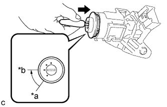
Text in Illustration *a LOCK *b ACC Make sure that the ignition switch lock cylinder assembly is in the ACC position.
-
Install the ignition switch lock cylinder assembly to the steering column upper bracket assembly.
-
Make sure that the ignition switch lock cylinder assembly is securely installed.
-
-
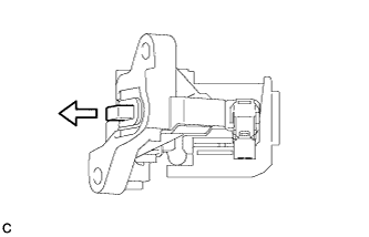
INSTALL KEY INTERLOCK SOLENOID (w/o Smart Key System)
-
Engage the claw to install the key interlock solenoid to the steering column upper bracket assembly.
-
Install the screw.
-
-
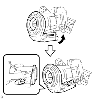
INSTALL UNLOCK WARNING SWITCH ASSEMBLY (w/o Smart Key System)
-
Slide the unlock warning switch assembly and engage the 2 claws to install the unlock warning switch assembly to the steering column upper bracket assembly as shown in the illustration.
-
-
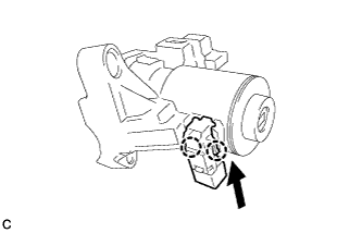
INSTALL TRANSPONDER KEY AMPLIFIER (w/o Smart Key System)
-
Align the transponder key amplifier with the steering column upper bracket assembly. Tilt the transponder key amplifier slightly and slide it into position.
-
Push the transponder key amplifier, and engage the 2 claws to install the transponder key amplifier to the steering column upper bracket assembly.
-
-
INSPECT STEERING LOCK OPERATION (w/o Smart Key System)
-
Check that the steering lock mechanism is activated when the key is removed.
-
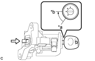
Text in Illustration *a LOCK *b ACC Check that the steering lock mechanism is deactivated when the key is inserted and turned to the ACC position.
Tech Tips
If there is any abnormality, replace the ignition switch lock cylinder assembly or steering column upper bracket assembly.
-
-
INSTALL POWER STEERING ECU ASSEMBLY (for 2AR without Wireless Door Lock)
-
Install the power steering ECU assembly to the steering column assembly with the 2 bolts.
- Torque:
- 19 N*m { 189 kgf*cm, 14 ft.*lbf }
-
Connect the 4 connectors to the power steering ECU assembly.
-
-
INSTALL POWER STEERING MOTOR ASSEMBLY (for 2AR without Wireless Door Lock)
-
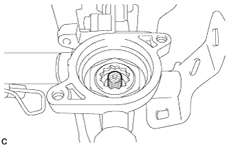
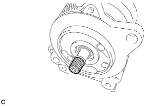
Apply grease to the serrated part of the electric power steering column sub-assembly.
Note
First wipe off the existing grease from the serrated part, and then apply the dedicated grease supplied with a new power steering motor assembly or electric power steering column sub-assembly.
-
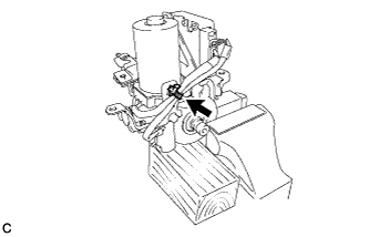
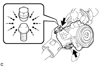
Temporarily install the power steering motor assembly to the electric power steering column sub-assembly with the 2 bolts.
Note
When temporarily installing the 2 bolts to the power steering motor assembly, do not tighten them all the way down.
-
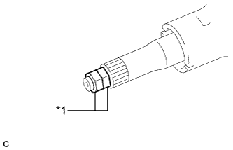
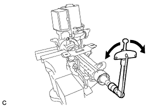
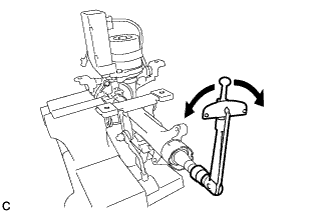
Text in Illustration *1 Service Nut Install the 2 service nuts to the steering main shaft.
Recommended service nut Thread diameter 12.0 mm (0.472 in.) Thread pitch 1.25 mm (0.0492 in.) -
Simultaneously to rotate the service nut that was installed first counterclockwise and rotate the service nut that was installed second clockwise to lock them.
Note
Do not apply excess torque to the service nuts by using a tool such as an impact wrench.
Tech Tips
These nuts are installed to turn the steering main shaft. They should be removed after inspecting the steering main shaft rotating torque.
-
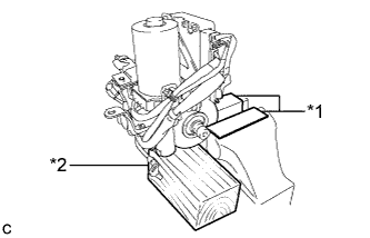
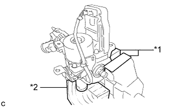
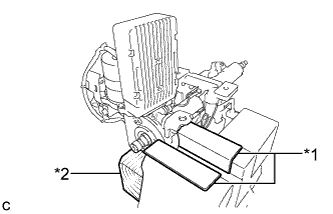
Text in Illustration *1 Aluminum Plate *2 Wooden Block Secure the steering column assembly in a vice using aluminum plates and wooden block as shown in the illustration.
Note
-
Do not overtighten the vice, as the steering column assembly may become deformed.
-
Secure the steering column assembly so that power steering motor assembly is directly upright.
-
Support the steering column assembly with a wooden block or similar item to ensure that it does not fall.
-
-
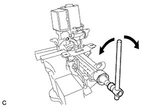
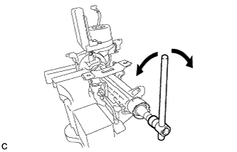
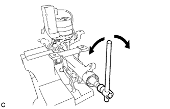
Turn the steering main shaft once 180 degrees to the left and then 180 degrees to the right at a speed of 60 rpm, and repeat 2 to 3 times to adjust the axis of the power steering motor assembly.
-
Tighten the 2 bolts.
- Torque:
- 19 N*m { 189 kgf*cm, 14 ft.*lbf }
Note
Make sure not to move the power steering motor assembly after adjusting the axis.
-
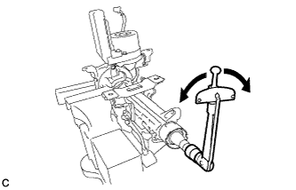
Measure the turning torque of the steering main shaft.
- Torque:
- Turning torque
- 0.9 to 1.7 N*m { 10 to 17 kgf*cm, 8 to 15 in.*lbf }
Note
Ensure that there is no abnormal resistance during rotation.
If the torque is not as specified, readjust the axis of the power steering motor assembly.
-
Remove the 2 service nuts from the steering main shaft.
-
Connect the 2 connectors to the power steering ECU assembly.
-
Install a new wire harness clamp.
-
Engage the wire harness clamp to the electric power steering column sub-assembly.
-
-
INSTALL ECU WIRE SUB-ASSEMBLY (for 2AR without Wireless Door Lock)
-
Engage the 2 wire harness clamps to install the ECU wire sub-assembly.
-
Connect the 2 connectors to the power steering ECU assembly.
-
-
INSTALL POWER STEERING ECU WITH MOTOR ASSEMBLY (for 2AR with Wireless Door Lock)
-
Install a new electric power steering motor shaft damper to the electric power steering column sub-assembly.
-
Install a new electric power steering motor shaft spacer to the electric power steering column sub-assembly.
-
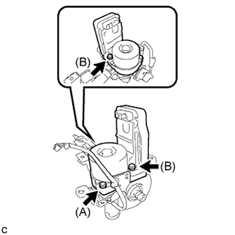
Temporarily install the power steering ECU with motor assembly to the electric power steering column sub-assembly with 3 bolts.
Note
-
Bolt (A) is shorter than bolt (B). Make sure to install them to the correct positions.
-
When temporarily installing the 3 bolts to the power steering motor assembly, do not tighten them all the way down.
-
-
Text in Illustration *1 Service Nut Install the 2 service nuts to the steering main shaft.
Recommended service nut Thread diameter 12.0 mm (0.472 in.) Thread pitch 1.25 mm (0.0492 in.) -
Simultaneously to rotate the service nut that was installed first counterclockwise and rotate the service nut that was installed second clockwise to lock them.
Note
Do not apply excess torque to the service nuts by using a tool such as an impact wrench.
Tech Tips
These nuts are installed to turn the steering main shaft. They should be removed after inspecting the steering main shaft rotating torque.
-
Text in Illustration *1 Aluminum Plate *2 Wooden Block Secure the steering column assembly in a vice using aluminum plates and wooden block as shown in the illustration.
Note
-
Do not overtighten the vice, as the steering column assembly may become deformed.
-
Secure the steering column assembly so that power steering ECU assembly with motor is directly upright.
-
Support the steering column assembly with a wooden block or similar item to ensure that it does not fall.
-
-
Turn the steering main shaft once 180 degrees to the left and then 180 degrees to the right at a speed of 60 rpm, and repeat 2 to 3 times to adjust the axis of the power steering ECU with motor assembly.
-
Tighten the 3 bolts.
- Torque:
- 19 N*m { 189 kgf*cm, 14 ft.*lbf }
Note
Make sure not to move the power steering motor assembly after adjusting the axis.
-
Measure the turning torque of the steering main shaft.
- Torque:
- Turning torque
- 1.0 to 1.8 N*m { 10 to 18 kgf*cm, 9 to 15 in.*lbf }
Note
Ensure that there is no abnormal resistance during rotation.
If the torque is not as specified, readjust the axis of the power steering ECU with motor assembly.
-
Remove the 2 service nuts from the steering main shaft.
-
Connect the connector to the power steering ECU with motor assembly.
-
-
INSTALL ECU WIRE SUB-ASSEMBLY (for 2AR with Wireless Door Lock)
-
Engage the 2 wire harness clamps to install the ECU wire sub-assembly.
-
Connect the 2 connectors to the power steering ECU with motor assembly.
-
-
INSTALL POWER STEERING ECU PROTECTOR (for 2AR with Wireless Door Lock)
-
Install a new power steering ECU protector to the power steering ECU with motor assembly.
-
-
INSTALL POWER STEERING ECU ASSEMBLY (for 2GR)
-
Install the power steering ECU assembly to the power steering motor assembly with the 2 new bolts.
- Torque:
- 20 N*m { 204 kgf*cm, 15 ft.*lbf }
-
Install the 3 new bolts.
- Torque:
- 3.2 N*m { 33 kgf*cm, 28 in.*lbf }
-
Engage the 4 claws to install the new protector.
-
-
INSTALL POWER STEERING ECU WITH MOTOR ASSEMBLY (for 2GR)
-
Text in Illustration *1 Service Nut Install the 2 service nuts to the steering main shaft.
Recommended service nut Thread diameter 12.0 mm (0.472 in.) Thread pitch 1.25 mm (0.0492 in.) -
Simultaneously to rotate the service nut that was installed first counterclockwise and rotate the service nut that was installed second clockwise to lock them.
Note
Do not apply excess torque to the service nuts by using a tool such as an impact wrench.
Tech Tips
These nuts are installed to turn the steering main shaft. They should be removed after inspecting the steering main shaft rotating torque.
-
Install a new O-ring to the power steering ECU with motor assembly.
-
Apply grease to the splines of the power steering ECU with motor assembly.
Note
First wipe off the existing grease from the splines, and then apply the dedicated grease supplied with a new power steering motor assembly or electric power steering column sub-assembly.
-
Insert the power steering ECU with motor assembly into the splines of the electric power steering column sub-assembly.
Note
Do not damage the gears.
-
Text in Illustration *1 Aluminum Plate *2 Wooden Block Secure the steering column assembly in a vice using aluminum plates and wooden block as shown in the illustration.
Note
-
Do not overtighten the vice, as the steering column assembly may become deformed.
-
Secure the steering column assembly so that power steering motor assembly is directly upright.
-
Support the steering column assembly with a wooden block or similar item to ensure that it does not fall.
-
-
Temporarily install the power steering ECU with motor assembly to the electric power steering column sub-assembly with 2 new bolts while rotating the steering main shaft at approximately 4 rpm.
Note
When temporarily installing the 2 bolts to the power steering motor assembly, do not tighten them all the way down.
-
Rotate the steering main shaft 120 to 240 degrees at approximately 4 rpm.
-
Rotate the steering main shaft 180 degrees clockwise and counterclockwise at approximately 4 rpm and repeat this operation 2 or 3 times to align the power steering ECU with motor assembly.
-
Tighten the 2 bolts.
- Torque:
- 19 N*m { 194 kgf*cm, 14 ft.*lbf }
Note
Make sure not to move the power steering motor assembly after adjusting the axis.
-
Measure the turning torque of the steering main shaft.
- Torque:
- Turning torque
- 1.2 to 1.7 N*m { 12 to 17 kgf*cm, 10 to 15 in.*lbf }
Note
Ensure that there is no abnormal resistance during rotation.
If the torque is not as specified, readjust the axis of the power steering ECU with motor assembly.
-
Remove the 2 service nuts from the steering main shaft.
-
Connect the 2 connectors to the power steering ECU assembly.
-
-
INSTALL ECU WIRE SUB-ASSEMBLY (for 2GR)
-
Engage the 2 wire harness clamps to install the new ECU wire sub-assembly.
-
Connect the 2 connectors to the power steering ECU with motor assembly.
-
-
INSTALL POWER STEERING ECU PROTECTOR (for 2GR)
-
Engage the 2 claws to install a new power steering ECU protector to the power steering ECU with motor assembly.
-
-
INSTALL STEERING COLUMN UPPER WITH SWITCH BRACKET ASSEMBLY (w/o Smart Key System)
-
Secure the steering column assembly in a vise.
-
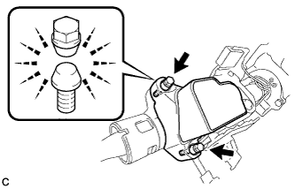
Temporarily install the steering column upper with switch bracket assembly to the steering column assembly with 2 new tapered-head bolts.
-
Tighten the 2 tapered-head bolts until the bolt heads break off.
-
-
INSTALL STEERING LOCK ACTUATOR ASSEMBLY (w/ Smart Key System)
Tech Tips
When replacing the steering lock actuator assembly, perform initialization Click here.
-
Secure the steering column assembly in a vise.
-
Temporarily install the steering lock actuator assembly to the steering column assembly with 2 new tapered-head bolts.
-
Tighten the 2 tapered-head bolts until the bolt heads break off.
-