STEERING COLUMN ASSEMBLY DISASSEMBLY

Note
-
When using a vise, do not overtighten it.
-
Do not drop the power steering motor assembly, strike it with tools or subject it to impacts.
-
If the power steering motor assembly is subjected to an impact, replace it with a new one.
-
Do not pull the wire harness of the electric power steering column sub-assembly.
-
Do not allow any moisture to come into contact with the power steering motor assembly.
-
Do not loosen any bolts not mentioned in the procedure.
-
REMOVE STEERING COLUMN UPPER WITH SWITCH BRACKET ASSEMBLY (w/o Smart Key System)
-
Using a center punch, mark the center of the 2 tapered-head bolts.
-
Using a 3 to 4 mm (0.118 to 0.157 in.) diameter drill bit, drill a hole in each tapered-head bolt.
-
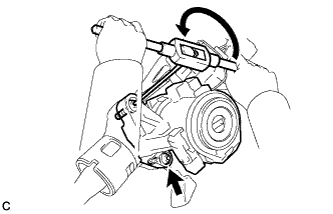
Using a screw extractor, remove each tapered-head bolt, and then remove the steering column upper with switch bracket assembly from the steering column assembly.
-
-
REMOVE STEERING LOCK ACTUATOR ASSEMBLY (w/ Smart Key System)
-
Using a center punch, mark the center of the 2 tapered-head bolts.
-
Using a 3 to 4 mm (0.118 to 0.157 in.) diameter drill bit, drill a hole in each tapered-head bolt.
-
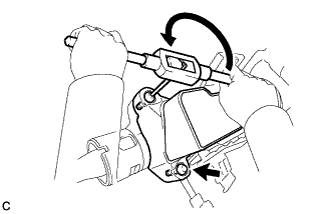
Using a screw extractor, remove each tapered-head bolt, and then remove the steering lock actuator assembly from the steering column assembly.
-
-
REMOVE ECU WIRE SUB-ASSEMBLY (for 2AR without Wireless Door Lock)
-
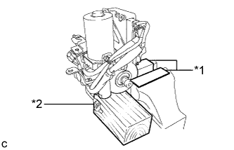
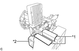
Text in Illustration *1 Aluminum Plate *2 Wooden Block Secure the steering column assembly in a vice using aluminum plates as shown in the illustration.
Note
-
Do not overtighten the vice, as the steering column assembly may become deformed.
-
Secure the power steering motor assembly so that it is directly upright.
-
Support the steering column assembly with a wooden block or similar item to ensure that it does not fall.
-
-
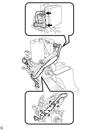
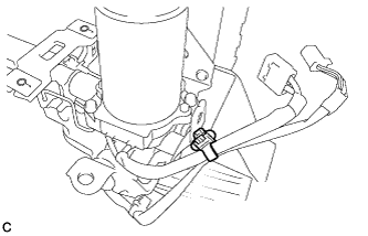
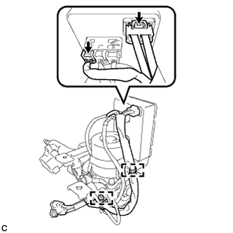
Disconnect the 2 connectors from the power steering ECU assembly.
-
Disengage the 2 wire harness clamps to remove the ECU wire sub-assembly.
-
-
REMOVE POWER STEERING MOTOR ASSEMBLY (for 2AR without Wireless Door Lock)
-
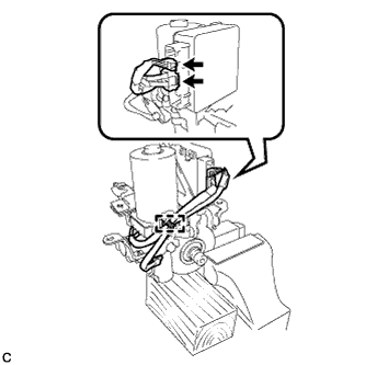
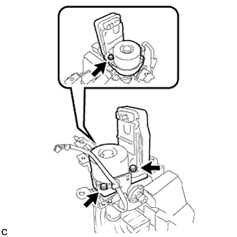
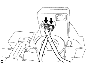
Disconnect the 2 connectors from the power steering ECU assembly.
-
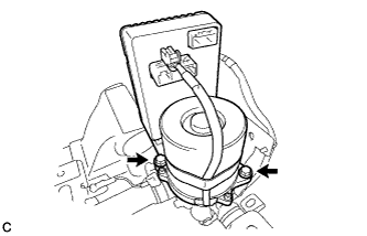
Disengage the wire harness clamp from the electric power steering column sub-assembly.
-
Remove the wire harness clamp.
-
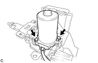
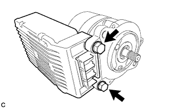
Remove the 2 bolts and power steering motor assembly from the electric power steering column sub-assembly.
-
-
REMOVE POWER STEERING ECU ASSEMBLY (for 2AR without Wireless Door Lock)
-
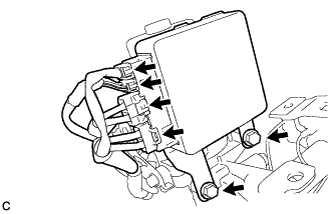
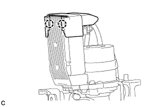
Disconnect the 4 connectors from the power steering ECU assembly.
-
Remove the 2 bolts to remove the power steering ECU assembly from the steering column assembly.
-
-
REMOVE POWER STEERING ECU PROTECTOR (for 2AR with Wireless Door Lock)
-
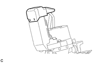
Remove the power steering ECU protector from the power steering ECU with motor assembly.
-
-
REMOVE ECU WIRE SUB-ASSEMBLY (for 2AR with Wireless Door Lock)
-
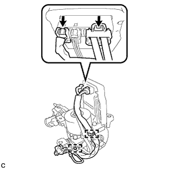
Disconnect the 2 connectors from the power steering ECU with motor assembly.
-
Disengage the 2 wire harness clamps to remove the ECU wire sub-assembly.
-
-
REMOVE POWER STEERING ECU WITH MOTOR ASSEMBLY (for 2AR with Wireless Door Lock)
-
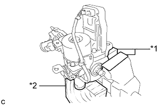
Text in Illustration *1 Aluminum Plate *2 Wooden Block Secure the steering column assembly in a vice using aluminum plates and wooden block as shown in the illustration.
Note
-
Do not overtighten the vice, as the steering column assembly may become deformed.
-
Secure the power steering motor assembly so that it is directly upright.
-
Support the steering column assembly with a wooden block or similar item to ensure that it does not fall.
-
-
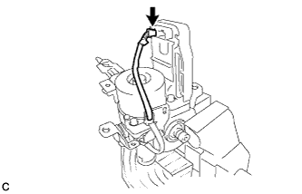
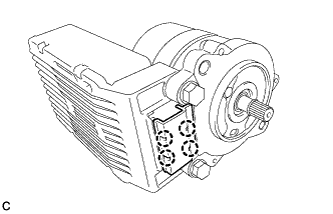
Disconnect the connector from the power steering ECU with motor assembly.
-
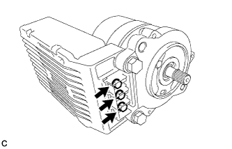
Remove the 3 bolts and power steering ECU with motor assembly from the electric power steering column sub-assembly.
-
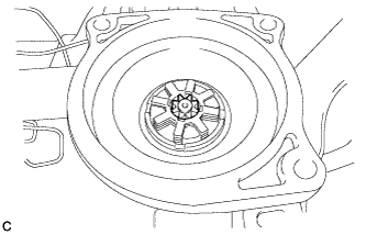
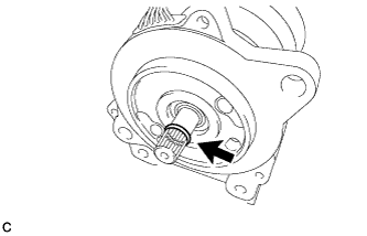
Remove the electric power steering motor shaft spacer from the electric power steering column sub-assembly.
-
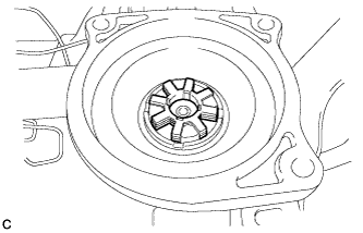
Remove the electric power steering motor shaft damper from the electric power steering column sub-assembly.
-
-
REMOVE POWER STEERING ECU PROTECTOR (for 2GR)
-
Disengage the 2 claws to remove the power steering ECU protector from the power steering ECU with motor assembly.
-
-
REMOVE ECU WIRE SUB-ASSEMBLY (for 2GR)
-
Disconnect the 2 connectors from the power steering ECU with motor assembly.
-
Disengage the 2 wire harness clamps to remove the ECU wire sub-assembly.
-
-
REMOVE POWER STEERING ECU WITH MOTOR ASSEMBLY (for 2GR)
-
Text in Illustration *1 Aluminum Plate *2 Wooden Block Secure the steering column assembly in a vice using aluminum plates as shown in the illustration.
Note
-
Do not overtighten the vice, as the steering column assembly may become deformed.
-
Secure the power steering motor assembly so that it is directly upright.
-
Support the steering column assembly with a wooden block or similar item to ensure that it does not fall.
-
-
Disconnect the 2 connectors from the power steering ECU with motor assembly.
-
Remove the 2 bolts and power steering ECU with motor assembly from the electric power steering column sub-assembly.
-
Remove the O-ring from the power steering ECU with motor assembly.
-
-
REMOVE POWER STEERING ECU ASSEMBLY (for 2GR)
-
Disengage the 4 claws to remove the protector.
-
Remove the 3 bolts.
-
Remove the 2 bolts to remove the power steering ECU assembly from the power steering motor assembly.
-
-
REMOVE TRANSPONDER KEY AMPLIFIER (w/o Smart Key System)
-
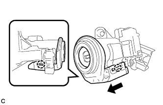
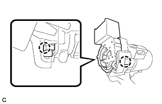
Slide the transponder key amplifier, disengage the 2 claws and then remove the transponder key amplifier as shown in the illustration.
-
-
REMOVE UNLOCK WARNING SWITCH ASSEMBLY (w/o Smart Key System)
-
Insert the key.
-
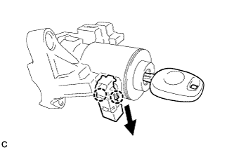
Disengage the 2 claws and slide the unlock warning switch assembly to remove it as shown in the illustration.
-
-
REMOVE KEY INTERLOCK SOLENOID (w/o Smart Key System)
-
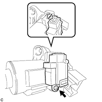
Remove the screw.
-
Disengage the claw to remove the key interlock solenoid from the steering column upper bracket assembly.
-
-
REMOVE IGNITION SWITCH LOCK CYLINDER ASSEMBLY (w/o Smart Key System)
-
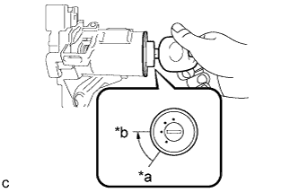
Text in Illustration *a LOCK *b ACC Turn the ignition switch lock cylinder assembly to the ACC position.
-
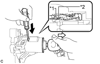
Text in Illustration *1 Claw *2 Stopper 
Push 
Pull Insert a screwdriver into the hole of the steering column upper bracket assembly as shown in the illustration. Pull the ignition switch lock cylinder assembly until its claw contacts the stopper of the steering column upper bracket assembly.
Note
Make sure to pull the ignition switch lock cylinder assembly until its claw contacts the stopper of the steering column upper bracket assembly. Failure to do so will affect later work operations.
-
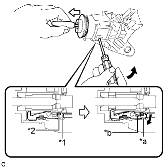
Text in Illustration *1 Claw *2 Stopper *a Claw disengaged *b Driver Insertion Hole Tilt Pull out Insert a screwdriver into the hole of the steering column upper bracket assembly. Tilt the screwdriver as shown in the illustration to disengage the claw of the ignition switch lock cylinder assembly, and pull out the ignition switch lock cylinder assembly from the steering column upper bracket assembly.
-
-
REMOVE IGNITION OR STARTER SWITCH ASSEMBLY (w/o Smart Key System)
-
Disengage the 2 claws to remove the ignition or starter switch assembly from the steering column upper bracket assembly.
-