STEERING COLUMN ASSEMBLY REMOVAL

CAUTION:
Some of these service operations affect the SRS airbag system. Read the precautionary notices concerning the SRS airbag system before servicing the steering column Click here.
-
PRECAUTION
-
TURN FRONT WHEELS TO FACE STRAIGHT AHEAD
-
REMOVE FRONT WHEEL LH
-
REMOVE HORN BUTTON ASSEMBLY
-
REMOVE STEERING WHEEL ASSEMBLY (for 3 Spoke)
-
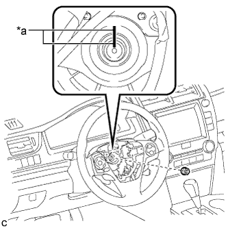
Text in Illustration *a Matchmark Remove the steering wheel assembly set nut.
-
Put matchmarks on the steering wheel assembly and steering main shaft.
-
Disconnect the connectors from the spiral cable sub-assembly and steering wheel assembly.
-
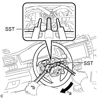
Text in Illustration *a Turn *b Hold Using SST, remove the steering wheel assembly.
- SST
- 09950-50013 ( 09951-05010, 09952-05010, 09953-05020, 09954-05070 )
Note
Apply a small amount of grease to the threads and tip of SST (09953-05020) before use.
-
-
REMOVE STEERING WHEEL ASSEMBLY (for 4 Spoke)
-
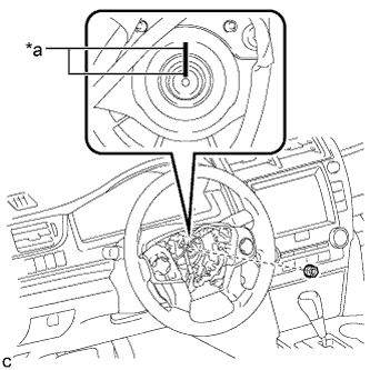
Text in Illustration *a Matchmark Remove the steering wheel assembly set nut.
-
Put matchmarks on the steering wheel assembly and steering main shaft.
-
Disconnect the connectors from the spiral cable sub-assembly.
-
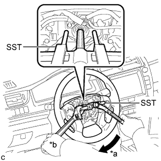
Text in Illustration *a Turn *b Hold Using SST, remove the steering wheel assembly.
- SST
- 09950-50013 ( 09951-05010, 09952-05010, 09953-05020, 09954-05070 )
Note
Apply a small amount of grease to the threads and tip of SST (09953-05020) before use.
-
-
REMOVE LOWER NO. 1 INSTRUMENT PANEL AIRBAG ASSEMBLY
-
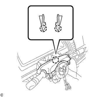
REMOVE LOWER STEERING COLUMN COVER
-
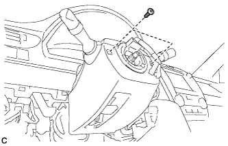
Remove the 2 screws.
-
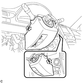
Push the right and left sides of the lower steering column cover, and disengage the 2 claws.
-
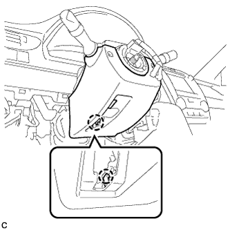
Insert a finger into the opening of the tilt lever of the lower steering column cover to disengage the claw and remove the lower steering column cover.
-
-
REMOVE UPPER STEERING COLUMN COVER
-
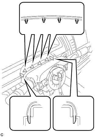
Disengage the 4 clips and 2 guides from the upper steering column cover.
-
Disengage the 2 claws to remove the upper steering column cover.
-
-
REMOVE TURN SIGNAL SWITCH ASSEMBLY WITH SPIRAL CABLE SUB-ASSEMBLY
Note
-
Do not replace the spiral cable with sensor sub-assembly with the battery connected and the ignition switch on (IG).
-
Do not rotate the spiral cable with sensor sub-assembly without the steering wheel with the battery connected and the ignition switch on (IG).
-
Ensure that the steering wheel is installed and aligned straight when inspecting the steering sensor.
-
Disconnect the connectors from the turn signal switch assembly with spiral cable sub-assembly.
-
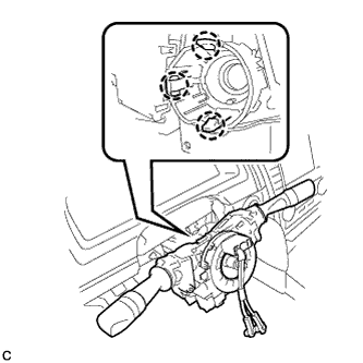
Disengage the 3 claws to remove the turn signal switch assembly with spiral cable sub-assembly from the steering post assembly.
-
-
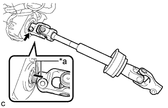
SEPARATE STEERING INTERMEDIATE SHAFT ASSEMBLY
-
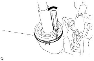
Using a screwdriver, loosen the clamp as shown in the illustration.
-
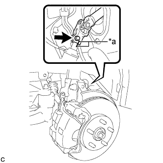
Text in Illustration *a Matchmark Put matchmarks on the steering intermediate shaft assembly and the steering link assembly.
-
Remove the bolt and separate the steering intermediate shaft assembly from the steering link assembly.
-
-
REMOVE NO. 2 AIR DUCT SUB-ASSEMBLY
-
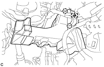
Disengage the 2 claws and guide to remove the No. 2 air duct sub-assembly.
-
-
REMOVE STEERING POST ASSEMBLY
-
Disconnect the connectors and disengage the wire harness clamps from the steering post assembly.
-
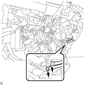
Disconnect the 2 connectors.
-
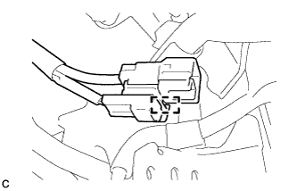
Disengage the clamp.
-
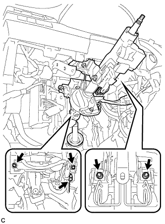
Remove the bolt to separate the ground wire.
-
Remove the 4 nuts and the steering post assembly.
-
-
REMOVE STEERING INTERMEDIATE SHAFT ASSEMBLY
-
Text in Illustration *a Matchmark Remove the bolt and slide the steering intermediate shaft assembly.
Note
Do not separate the steering intermediate shaft assembly from the steering column assembly.
-
Put matchmarks on the steering intermediate shaft assembly and the steering post assembly.
-
Remove the steering intermediate shaft assembly from the steering column assembly.
-