POWER STEERING ECU (w/ Wireless Door Lock System) REMOVAL

-
REMOVE STEERING COLUMN ASSEMBLY
-
REMOVE STEERING COLUMN UPPER WITH SWITCH BRACKET ASSEMBLY (w/o Smart Key System)
-
Using a center punch, mark the center of the 2 tapered-head bolts.
-
Using a 3 to 4 mm (0.118 to 0.157 in.) diameter drill bit, drill a hole in each tapered-head bolt.
-
Using a screw extractor, remove each tapered-head bolt, and then remove the steering column upper with switch bracket assembly from the steering column assembly.
-
-
REMOVE STEERING LOCK ACTUATOR ASSEMBLY (w/ Smart Key System)
-
Using a center punch, mark the center of the 2 tapered-head bolts.
-
Using a 3 to 4 mm (0.118 to 0.157 in.) diameter drill bit, drill a hole in each tapered-head bolt.
-
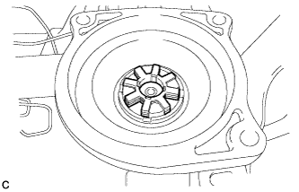
Using a screw extractor, remove each tapered-head bolt, and then remove the steering lock actuator assembly from the steering column assembly.
-
-
REMOVE POWER STEERING ECU PROTECTOR (for 2AR)
-
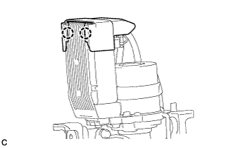
Remove the power steering ECU protector from the power steering ECU with motor assembly.
-
-
DISCONNECT ECU WIRE SUB-ASSEMBLY (for 2AR)
-
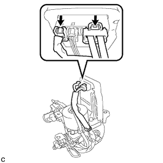
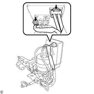
Disconnect the 2 connectors from the power steering ECU assembly.
-
-
REMOVE POWER STEERING ECU WITH MOTOR ASSEMBLY (for 2AR)
-
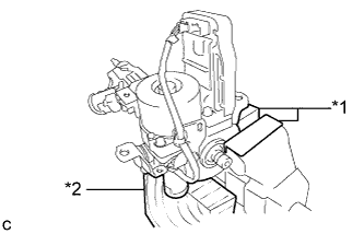
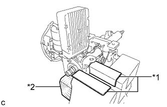
Text in Illustration *1 Aluminum Plate *2 Wooden Block Secure the steering column assembly in a vice using aluminum plates and wooden block as shown in the illustration.
Note
-
Do not overtighten the vice, as the steering column assembly may become deformed.
-
Secure the power steering motor assembly so that it is directly upright.
-
Support the steering column assembly with a wooden block or similar item to ensure that it does not fall.
-
-
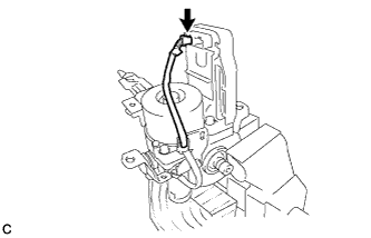
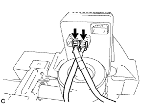
Disconnect the connector from the power steering ECU with motor assembly.
-
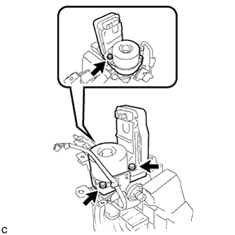
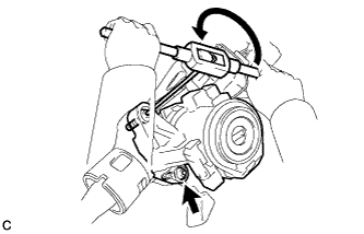
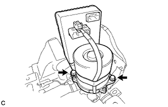
Remove the 3 bolts and power steering ECU with motor assembly from the electric power steering column sub-assembly.
-
Remove the electric power steering motor shaft spacer from the electric power steering column sub-assembly.
-
Remove the electric power steering motor shaft damper from the electric power steering column sub-assembly.
-
-
REMOVE POWER STEERING ECU PROTECTOR (for 2GR)
-
Disengage the 2 claws to remove the power steering ECU protector from the power steering ECU with motor assembly.
-
-
DISCONNECT ECU WIRE SUB-ASSEMBLY (for 2GR)
-
Disconnect the 2 connectors from the power steering ECU assembly.
-
-
REMOVE POWER STEERING ECU WITH MOTOR ASSEMBLY (for 2GR)
-
Text in Illustration *1 Aluminum Plate *2 Wooden Block Secure the steering column assembly in a vice using aluminum plates as shown in the illustration.
Note
-
Do not overtighten the vice, as the steering column assembly may become deformed.
-
Secure the power steering motor assembly so that it is directly upright.
-
Support the steering column assembly with a wooden block or similar item to ensure that it does not fall.
-
-
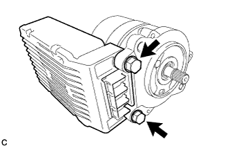
Disconnect the 2 connectors from the power steering ECU with motor assembly.
-
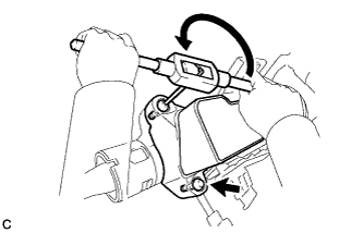
Remove the 2 bolts and power steering ECU with motor assembly from the electric power steering column sub-assembly.
-
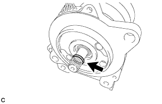
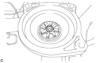
Remove the O-ring from the power steering ECU with motor assembly.
-
-
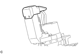
REMOVE POWER STEERING ECU ASSEMBLY (for 2GR)
-
Disengage the 4 claws to remove the protector.
-
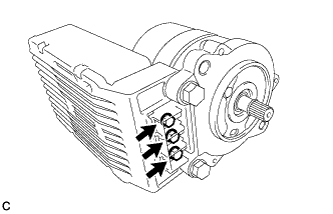
Remove the 3 bolts.
-
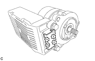
Remove the 2 bolts to remove the power steering ECU assembly from the power steering motor assembly.
-