PARKING BRAKE CABLE INSTALLATION

-
INSTALL NO. 2 PARKING BRAKE CABLE CLAMP
-
Install a new No. 2 parking brake cable clamp to the No. 3 parking brake cable assembly.
-
-
INSTALL NO. 3 PARKING BRAKE CABLE ASSEMBLY
-
Install the No. 3 parking brake cable assembly with the 4 bolts and nut.
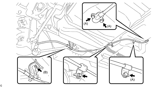
- Torque:
- Bolt (A)
- 8.5 N*m { 87 kgf*cm, 75 in.*lbf }
- Bolt (B) and Nut
- 6.0 N*m { 61 kgf*cm, 53 in.*lbf }
-
Install the No. 3 parking brake cable assembly with the bolt.
- Torque:
- 8.0 N*m { 82 kgf*cm, 71 in.*lbf }
-
Install the clip to the No. 3 parking brake cable assembly.
-
-
INSTALL NO. 2 FLOOR UNDER COVER (for LH Side)
-
w/ Floor Under Cover:
-
Install the No. 2 floor under cover with the 2 bolts, 3 nuts and 2 clips.
- Torque:
- Bolt
- 12 N*m { 122 kgf*cm, 9 ft.*lbf }
- Nut
- 4.0 N*m { 41 kgf*cm, 35 in.*lbf }
-
-
-
INSTALL NO. 1 FLOOR UNDER COVER (for RH Side)
-
Install the No. 1 floor under cover with the 2 bolts, 3 nuts and 2 clips.
- Torque:
- Bolt
- 12 N*m { 122 kgf*cm, 9 ft.*lbf }
- Nut
- 4.0 N*m { 41 kgf*cm, 35 in.*lbf }
-
-
INSTALL PARKING BRAKE SHOE LEVER
-
INSTALL FRONT NO. 2 FLOOR HEAT INSULATOR (for 2AR-FE)
-
Install the front No. 2 floor heat insulator with the 3 nuts.
- Torque:
- 4.9 N*m { 50 kgf*cm, 43 in.*lbf }
-
-
INSTALL FRONT EXHAUST PIPE ASSEMBLY (for 2AR-FE)
-
INSTALL NO. 4 PARKING BRAKE CABLE ASSEMBLY
-
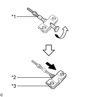
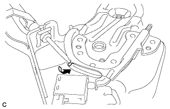
Text in Illustration *1 No. 4 Parking Brake Cable Assembly *2 Rubber Boot *3 Parking Brake Equalizer Install the No. 4 parking brake cable assembly to the parking brake equalizer.
-
Slide the parking brake equalizer and rubber boot as shown in the illustration.
Note
Make sure that the rubber boot is securely inserted into the groove of the No. 4 parking brake cable assembly.
-
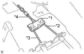
Text in Illustration *1 Parking Brake Equalizer *2 No. 2 Parking Brake Cable Assembly *3 No. 3 Parking Brake Cable Assembly *4 No. 4 Parking Brake Cable Assembly Connect the No. 3 parking brake cable assembly to the parking brake equalizer.
-
Connect the No. 2 parking brake cable assembly to the parking brake equalizer.
-
-
INSTALL NO. 4 CROSS MEMBER FLOOR REINFORCEMENT SUB-ASSEMBLY
-
Install the No. 4 cross member floor reinforcement sub-assembly with the 8 bolts.
- Torque:
- 19 N*m { 189 kgf*cm, 14 ft.*lbf }
-
Install the floor carpet.
-
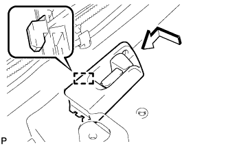
Engage the guide to connect the fuel lid lock open lever sub-assembly as shown in the illustration.
-
Install the screw.
-
-
INSTALL FLOOR CARPET HOOK
-
Engage the 6 claws to install the 6 floor carpet hooks.
-
Engage the 6 guides.
-
-
INSTALL DCM (TELEMATICS TRANSCEIVER) WITH BACK-UP BATTERY (w/ Manual (SOS) Switch)
-
Engage the 2 guides to the vehicle body to temporarily install the DCM (telematics transceiver) with back-up battery.
-
Install the DCM (telematics transceiver) with back-up battery with the bolt.
-
Connect each connector.
-
Engage the 3 clamps.
-
-
INSTALL AUDIO AMPLIFIER COVER (w/ Manual (SOS) Switch)
-
Install the audio amplifier cover with the 2 clips.
-
-
INSTALL STEREO COMPONENT AMPLIFIER ASSEMBLY WITH BRACKET (for 10 Speakers)
-
Engage the 2 guides to the vehicle body to temporarily install the stereo component amplifier assembly with bracket.
-
Install the stereo component amplifier assembly with bracket with the bolt.
-
Engage the clamp.
-
Connect each connector.
-
Connect the ground wire with the bolt.
- Torque:
- 8.0 N*m { 82 kgf*cm, 71 in.*lbf }
-
-
INSTALL AUDIO AMPLIFIER COVER (for 10 Speakers)
-
Install the audio amplifier cover with the 2 clips.
-
-
INSTALL FRONT SEAT ASSEMBLY LH
-
for TMMK Made Manual Seat: Click here
-
for TMMK Made Power Seat: Click here
-
for SIA Made Manual Seat: Click here
-
for SIA Made Power Seat: Click here
-
-
INSTALL FRONT SEAT ASSEMBLY RH
Tech Tips
Use the same procedure as for the LH side.
-
INSTALL CENTER PILLAR LOWER GARNISH LH
-
Engage the 2 claws and 3 clips to install the center pillar lower garnish LH.
-
-
CONNECT FRONT SEAT OUTER BELT ASSEMBLY LH
-
Install the floor anchor of the front seat outer belt assembly with the bolt.
- Torque:
- 42 N*m { 428 kgf*cm, 31 ft.*lbf }
-
Check if the ELR locks.
Note
The check should be performed with the front seat outer belt assembly installed.
-
With the belt assembly installed, check that the belt locks when it is pulled out quickly.
-
-
-
INSTALL LAP BELT OUTER ANCHOR COVER (for LH Side)
-
Engage the 3 claws to install the lap belt outer anchor cover.
-
-
INSTALL REAR DOOR OPENING TRIM WEATHERSTRIP LH
-
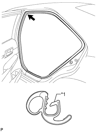
Text in Illustration *1 Alignment Mark (Pink) Align the alignment mark (Pink) on the weatherstrip with the protruding portion on the body indicated by the arrow in the illustration, and install the rear door opening trim weatherstrip LH.
Note
After installation, check that the corners fit correctly.
-
-
INSTALL REAR DOOR SCUFF PLATE LH
-
Engage the 6 claws to install the rear door scuff plate LH.
Tech Tips
Engage the claws from the rear side of the scuff plate.
-
-
INSTALL CENTER PILLAR LOWER GARNISH RH
Tech Tips
Use the same procedure as for the LH side.
-
CONNECT FRONT SEAT OUTER BELT ASSEMBLY RH
Tech Tips
Use the same procedure as for the LH side.
-
INSTALL LAP BELT OUTER ANCHOR COVER (for RH Side)
Tech Tips
Use the same procedure as for the LH side.
-
INSTALL REAR DOOR OPENING TRIM WEATHERSTRIP RH
-
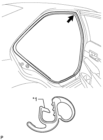
Text in Illustration *1 Alignment Mark (Blue) Align the alignment mark (Blue) on the weatherstrip with the protruding portion on the body indicated by the arrow in the illustration, and install the rear door opening trim weatherstrip RH.
Note
After installation, check that the corners fit correctly.
-
-
INSTALL REAR DOOR SCUFF PLATE RH
Tech Tips
Use the same procedure as for the LH side.
-
INSTALL NO. 1 PARKING BRAKE CABLE ASSEMBLY
-
Pass the No. 1 parking brake cable assembly through the parking brake pedal assembly.
-
Install the clip to the No. 1 parking brake cable assembly.
-
Temporarily install the adjusting nut.
-
Bend the parking brake pedal claw.
-
-
INSTALL PARKING BRAKE CONTROL PEDAL ASSEMBLY