REAR SUSPENSION MEMBER REMOVAL

-
REMOVE REAR WHEELS
-
REMOVE CENTER EXHAUST PIPE ASSEMBLY
-
for 2GR-FE: Click here
-
for 2AR-FE: Click here
-
-
REMOVE NO. 2 FLOOR UNDER COVER (w/ Floor Under Cover)
-
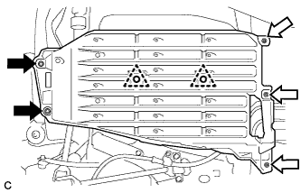
Remove the 2 bolts and 2 clips.
Text in Illustration 
Bolt 
Nut (attached to under cover) -
Disengage the 3 nuts and remove the No. 2 floor under cover.
-
-
REMOVE NO. 1 FLOOR UNDER COVER
-
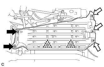
Remove the 2 bolts.
Text in Illustration Bolt Nut (attached to under cover) -
Disengage the 3 nuts and 2 clips, and remove the No. 1 floor under cover.
-
-
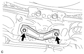
REMOVE NO. 3 EXHAUST PIPE SUPPORT BRACKET
-
Remove the 2 bolts and No. 3 exhaust pipe support bracket from the rear suspension member sub-assembly.
-
-
REMOVE JACK UP BRACKET (for 2GR-FE)
-
Remove the 2 bolts and jack up bracket from the rear suspension member sub-assembly.
-
-
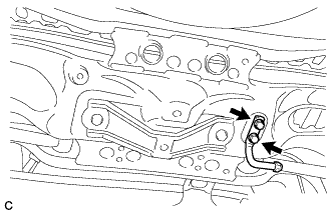
REMOVE REAR SUSPENSION MEMBER DAMPER (w/ Dynamic Damper)
-
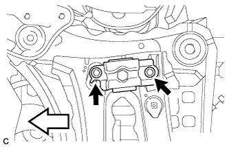
Remove the 2 bolts and rear suspension member damper from the rear suspension member sub-assembly.
Text in Illustration Front of the Vehicle
-
-
SEPARATE REAR STABILIZER LINK ASSEMBLY LH
-
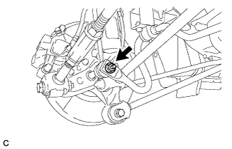
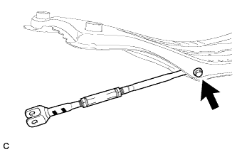
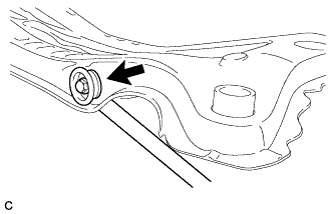
Remove the nut and separate the rear stabilizer link assembly LH from the rear stabilizer bar.
If the ball joint turns together with the nut, use a hexagon wrench to hold the stud.
-
-
SEPARATE REAR STABILIZER LINK ASSEMBLY RH
Tech Tips
Perform the same procedure as for the LH side.
-
REMOVE REAR STABILIZER BAR
-
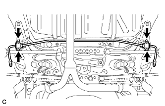
Remove the 4 bolts, rear stabilizer bar, 2 rear No. 1 stabilizer bar brackets, 2 rear No. 2 stabilizer bar brackets and 2 rear stabilizer bushings from the rear suspension member sub-assembly.
-
-
REMOVE REAR HEIGHT CONTROL SENSOR SUB-ASSEMBLY (w/ Height Control Sensor)
-
SEPARATE REAR NO. 2 SUSPENSION ARM ASSEMBLY LH
-
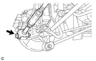
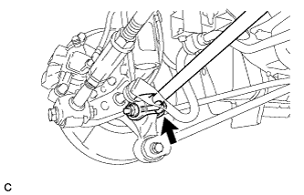
Remove the bolt and nut, and separate the rear No. 2 suspension arm assembly (outer side) from the rear axle carrier sub-assembly.
Note
When removing the bolt, keep the nut from rotating.
-
-
SEPARATE REAR NO. 2 SUSPENSION ARM ASSEMBLY RH
Tech Tips
Perform the same procedure as for the LH side.
-
REMOVE REAR NO. 2 SUSPENSION ARM ASSEMBLY LH
-
Remove the bolt and rear No. 2 suspension arm assembly from the rear suspension member sub-assembly.
-
-
REMOVE REAR NO. 2 SUSPENSION ARM ASSEMBLY RH
Tech Tips
Perform the same procedure as for the LH side.
-
SEPARATE REAR NO. 1 SUSPENSION ARM ASSEMBLY LH
-
Remove the bolt and nut, and separate the rear No. 1 suspension arm assembly (outer side) from the rear axle carrier sub-assembly.
Note
When removing the bolt, keep the nut from rotating.
-
-
SEPARATE REAR NO. 1 SUSPENSION ARM ASSEMBLY RH
Tech Tips
Perform the same procedure as for the LH side.
-
REMOVE REAR SUSPENSION MEMBER SUB-ASSEMBLY
-
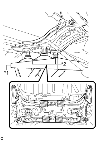
Text in Illustration *1 Engine Lifter *2 Attachment 
Attachment Placement Location Support the rear suspension member sub-assembly with an engine lifter using 4 attachments or equivalent tools as shown in the illustration.
Note
-
Make sure to secure the rear suspension member sub-assembly to prevent it from dropping.
-
Use the attachments to keep the rear suspension member sub-assembly level.
-
-
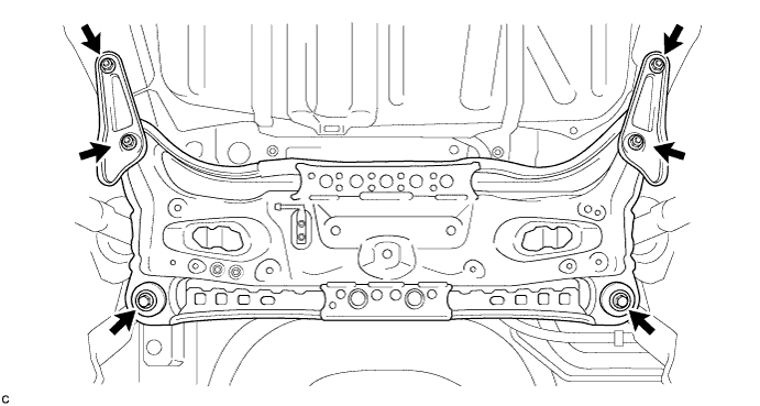
Remove the 2 bolts, 4 nuts, 2 rear suspension member lower stopper sub-assemblies and 2 rear suspension member lower stoppers.
-
Slowly lower the rear suspension member sub-assembly.
Note
When lowering the rear suspension member sub-assembly, be careful not to damage the vehicle body or other components installed on the vehicle.
-
w/ Member Cushion:
-
Remove the 2 differential support member cushions and 2 differential support member upper stoppers from the rear suspension member sub-assembly.
-
-
-
REMOVE REAR NO. 1 SUSPENSION ARM ASSEMBLY LH
-
Remove the bolt and rear No. 1 suspension arm assembly from the rear suspension member sub-assembly.
-
-
REMOVE REAR NO. 1 SUSPENSION ARM ASSEMBLY RH
Tech Tips
Perform the same procedure as for the LH side.
-
REMOVE REAR SUSPENSION MEMBER BODY MOUNTING FRONT CUSHION LH
-
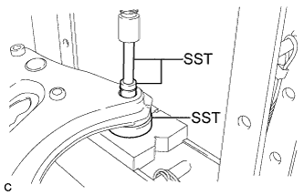
Using SST and a press, remove the rear suspension member body mounting front cushion LH from the rear suspension member sub-assembly.
- SST
- 09527-17011
- 09950-60010 ( 09951-00340 )
- 09950-70010 ( 09951-07100 )
-
-
REMOVE REAR SUSPENSION MEMBER BODY MOUNTING FRONT CUSHION RH
Tech Tips
Perform the same procedure as the LH side.
-
REMOVE REAR SUSPENSION MEMBER BODY MOUNTING REAR CUSHION (for LH Side)
-
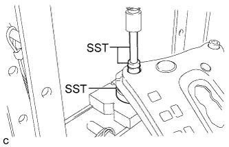
Using SST and a press, remove the rear suspension member body mounting rear cushion from the rear suspension member sub-assembly.
- SST
- 09527-17011
- 09950-60010 ( 09951-00340 )
- 09950-70010 ( 09951-07100 )
-
-
REMOVE REAR SUSPENSION MEMBER BODY MOUNTING REAR CUSHION (for RH Side)
Tech Tips
Perform the same procedure as the LH side.
-
REMOVE HOLE PLUG
-
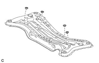
Remove the 4 hole plugs from the rear suspension member sub-assembly.
-