REAR AXLE CARRIER REMOVAL

Tech Tips
-
Use the same procedure for the RH side and LH side.
-
The procedure listed below is for the LH side.
-
REMOVE REAR WHEEL
-
SEPARATE REAR DISC BRAKE CALIPER ASSEMBLY
-
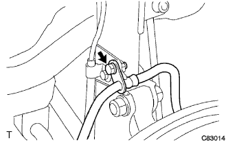
Remove the bolt and separate the rear flexible hose from the rear shock absorber.
-
Remove the 2 bolts, and separate the rear disc brake caliper assembly.
Note
Use wire or an equivalent tool to keep the rear disc brake caliper from hanging down by the flexible hose.
-
-
REMOVE PARKING BRAKE SHOE ADJUSTING HOLE PLUG
-
Remove the parking brake shoe adjusting hole plug.
-
-
REMOVE REAR DISC
-
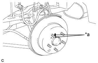
Text in Illustration *a Matchmark Put matchmarks on the rear disc and the rear axle hub.
-
Release the parking brake and remove the rear disc.
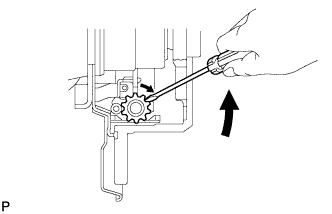
Tech Tips
If the disc cannot be removed easily, use a screwdriver to turn the shoe adjuster as shown in the illustration in order to contract the parking brake shoes.
-
-
DISCONNECT SKID CONTROL SENSOR WIRE
-
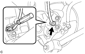
Using a screwdriver, disconnect the connector from the rear speed sensor.
Note
Be careful not to damage the rear speed sensor.
-
-
REMOVE REAR AXLE HUB AND BEARING ASSEMBLY
-
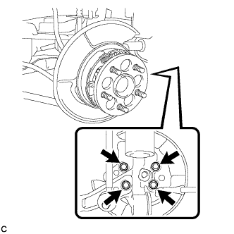
Remove the 4 bolts and the rear axle hub and bearing assembly from the rear axle carrier sub-assembly.
Note
Use wire or an equivalent tool to keep the parking brake assembly from hanging down by the parking brake cable assembly.
-
-
REMOVE REAR HEIGHT CONTROL SENSOR SUB-ASSEMBLY (w/ Height Control Sensor)
Tech Tips
It is necessary to remove the rear height control sensor sub-assembly when separating the rear No. 2 suspension arm assembly RH.
-
SEPARATE REAR STRUT ROD ASSEMBLY
-
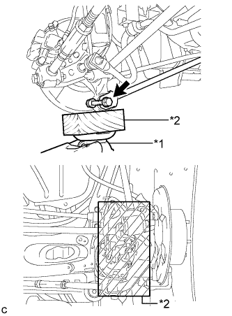
Text in Illustration *1 Jack *2 Wooden Block Use a jack and wooden block to support the rear axle carrier sub-assembly.
-
Remove the bolt and nut, and separate the rear strut rod assembly (rear side) from the rear axle carrier sub-assembly.
Note
When removing the bolt, keep the nut from rotating.
-
-
SEPARATE REAR NO. 2 SUSPENSION ARM ASSEMBLY
-
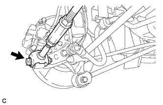
Remove the bolt and nut, and separate the rear No. 2 suspension arm assembly (outer side) from the rear axle carrier sub-assembly.
Note
When removing the bolt, keep the nut from rotating.
-
-
SEPARATE REAR NO. 1 SUSPENSION ARM ASSEMBLY
-
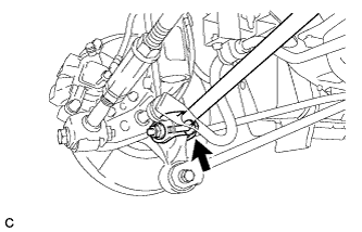
Remove the bolt and nut, and separate the rear No. 1 suspension arm assembly (outer side) from the rear axle carrier sub-assembly.
Note
When removing the bolt, keep the nut from rotating.
-
-
REMOVE REAR AXLE CARRIER SUB-ASSEMBLY
-
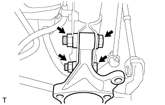
Remove the 2 bolts, 2 nuts and rear axle carrier sub-assembly from the rear shock absorber.
Note
When removing the nuts, keep the bolts from rotating.
-