DIFFERENTIAL CASE REASSEMBLY

-
INSTALL DIFFERENTIAL SIDE GEAR
-
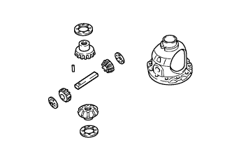
Coat the 2 front differential side gears, 2 No. 1 front differential side gear thrust washers, 2 front differential pinions and 2 front differential pinion thrust washers with ATF and install them to the front differential case.
-
-
INSTALL FRONT NO. 1 DIFFERENTIAL PINION SHAFT
-
Coat the front No. 1 differential pinion shaft with ATF, and install it to the front differential case.
-
-
INSPECT DIFFERENTIAL SIDE GEAR BACKLASH
-
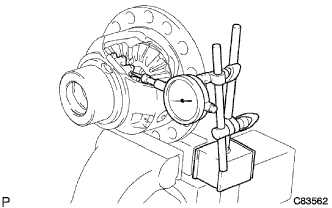
Hold the front differential case in a vise between aluminum plates.
Note
Do not overtighten the vise.
-
Place a dial indicator on the tip of the differential side gear tooth at a right angle.
-
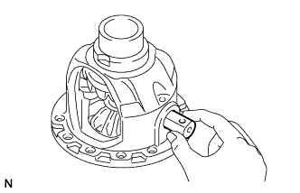
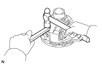
Hold the front differential pinion in the front differential case and measure the backlash of the differential side gear.
Standard backlash 0.05 to 0.2 mm (0.00197 to 0.00787 in.) Thrust Washer Thickness Thickness [mm (in.)] 1.00 (0.0394) 1.10 (0.0433) 1.20 (0.0472) 1.30 (0.0512) If the backlash is greater than the standard range, select another No. 1 front differential side gear thrust washer.
-
-
INSTALL FRONT DIFFERENTIAL PINION SHAFT STRAIGHT PIN
-
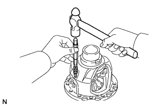
Using a 5 mm pin punch and hammer, install the front differential pinion shaft straight pin.
Note
Align the holes, and install the front differential pinion shaft straight pin.
-
Using a chisel and hammer, stake the front differential case.
Note
Stake the front differential case after adjusting the backlash.
-
-
INSTALL FRONT DIFFERENTIAL CASE REAR TAPERED ROLLER BEARING
-
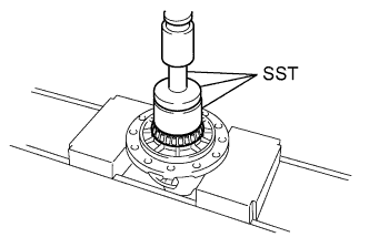
Using SST and a press, install a new front differential case rear tapered roller bearing (inner race) to the front differential case.
- SST
- 09710-30012 ( 09710-04081 )
- 09950-60010 ( 09951-00480 )
- 09950-70010 ( 09951-07100 )
Note
Do not damage the bearing cage during front differential case rear tapered roller bearing (inner race) installation.
-
Using SST and a hammer, install a new front differential case rear tapered roller bearing (outer race) to the transaxle case sub-assembly.
- SST
- 09950-60020 ( 09951-00810 )
- 09950-70010 ( 09951-07150 )
Note
Ensure that there is no clearance between the front differential case rear tapered roller bearing (outer race) and transaxle case sub-assembly.
-
-
INSTALL FRONT DIFFERENTIAL CASE FRONT TAPERED ROLLER BEARING
-
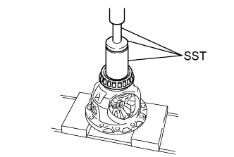
Using SST and a press, install a new front differential case front tapered roller bearing (inner race) to the front differential case.
- SST
- 09523-36010
- 09950-60010 ( 09951-00540 )
- 09950-70010 ( 09951-07100 )
Note
Do not damage the bearing cage during front differential case front tapered roller bearing (inner race) installation.
-
Install the shim to the transaxle housing.
-
Using SST and a hammer, install a new front differential case front tapered roller bearing (outer race) to the transaxle housing.
- SST
- 09950-60020 ( 09951-00790 )
- 09950-70010 ( 09951-07150 )
Note
Ensure that there is no clearance between the front differential case front tapered roller bearing (outer race) and transaxle housing.
-
-
ADJUST DIFFERENTIAL SIDE BEARING PRELOAD
-
Remove the seal packing from the contact surfaces between the transaxle housing and transaxle case sub-assembly.
-
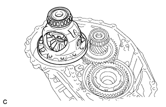
Install the front differential case to the transaxle case sub-assembly.
-
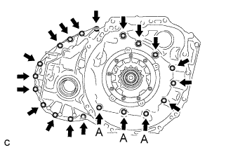
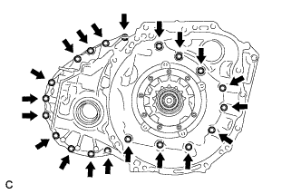
Install the transaxle housing to the transaxle case sub-assembly with the 20 bolts.
- Torque:
- Bolt A
- 23 N*m { 231 kgf*cm, 17 ft.*lbf }
- except Bolt A
- 31 N*m { 312 kgf*cm, 23 ft.*lbf }
-
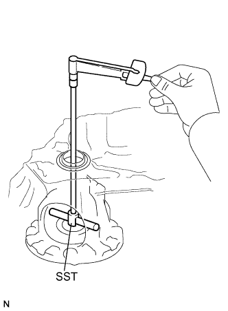
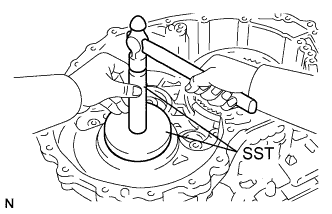
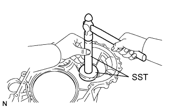
Using SST and a torque wrench, measure the turning torque of the differential side bearing while rotating SST at 10 rpm.
- SST
- 09564-33010
Turning torque TMC or AISIN AW made 1.3 to 1.7 N*m (14 to 17 kgf*cm, 12 to 15 in.*lbf) AWNC made 0.9 to 1.3 N*m (9 to 13 kgf*cm, 8 to 11 in.*lbf) Tech Tips
Three different automatic transaxle assembly models manufactured at different factories are available for this vehicle.
Referring to the introduction section, check the serial number. Confirm the factory at which the automatic transaxle assembly was manufactured according to the following table.
Serial Number Factory ##A######## AISIN AW made ##T######## TMC made ##N######## AWNC made If the turning torque is not within the specified range, refer to the table below to select a shim so that the turning torque is within the specified range.
Shim Thickness: mm (in.) Thickness Thickness Thickness Thickness 2.000 (0.0787) 2.225 (0.0876) 2.450 (0.0965) 2.675 (0.105) 2.025 (0.0797) 2.250 (0.0886) 2.475 (0.0974) 2.700 (0.106) 2.050 (0.0807) 2.275 (0.0896) 2.500 (0.0984) 2.725 (0.107) 2.075 (0.0817) 2.300 (0.0906) 2.525 (0.0994) 2.750 (0.108) 2.100 (0.0827) 2.325 (0.0915) 2.550 (0.100) 2.775 (0.109) 2.125 (0.0837) 2.350 (0.0925) 2.575 (0.101) 2.800 (0.110) 2.150 (0.0846) 2.375 (0.0935) 2.600 (0.102) 2.825 (0.111) 2.175 (0.0856) 2.400 (0.0945) 2.625 (0.103) 2.850 (0.112) 2.200 (0.0866) 2.425 (0.0955) 2.650 (0.104) 2.875 (0.113) -
Remove the 20 bolts and the transaxle housing from the transaxle case sub-assembly.
-
Remove the front differential case from the transaxle case sub-assembly.
-
-
INSTALL FRONT DIFFERENTIAL RING GEAR
-
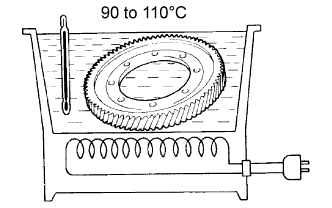
Using ATF and a heater, heat the front differential ring gear to 90 to 110°C (194 to 230°F).
Note
Do not heat the front differential ring gear to more than 110°C (230°F).
-
Clean the contact surface of the front differential case.
-
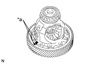
Align the matchmarks, set the front differential ring gear to the front differential case.
Text in Illustration *a Matchmark -
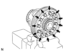
Install the 12 bolts.
- Torque:
- 120 N*m { 1224 kgf*cm, 89 ft.*lbf }
Note
-
Tighten the bolts after the front differential ring gear has cooled down sufficiently.
-
Tighten the bolts evenly in a diagonal pattern using several steps.
-
-
INSTALL TRANSAXLE CASE OIL SEAL
-
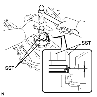
Coat the lip of a new transaxle case oil seal with a small amount of MP grease.
-
Using SST and a hammer, tap in the transaxle case oil seal.
- SST
- 09316-10010
- 09950-70010 ( 09951-07100 )
Oil seal tap in depth -0.5 to 0.5 mm (-0.0197 to 0.0197 in.) Note
Check that the transaxle case oil seal is installed in the correct direction.
-
-
INSTALL FRONT TRANSAXLE CASE OIL SEAL
-
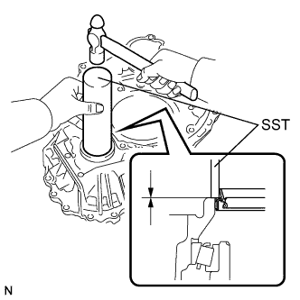
Coat the lip of a new front transaxle case oil seal with a small amount of MP grease.
-
Using SST and a hammer, tap in the front transaxle case oil seal.
- SST
- 09308-14010
Oil seal tap in depth -0.5 to 0.5 mm (-0.0197 to 0.0197 in.) Note
Check that the front transaxle case oil seal is installed in the correct direction.
-