AUTOMATIC TRANSAXLE ASSEMBLY REMOVAL

Note
If automatic transmission parts are replaced, refer to the Parts Replacement Compensation Table to determine if any additional operations are necessary Click here.
-
REMOVE ENGINE ASSEMBLY WITH TRANSAXLE
-
REMOVE FRONT DRIVE SHAFT ASSEMBLY LH
-
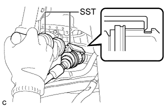
Using SST, remove the front drive shaft assembly LH.
- SST
- 09520-00031
- 09520-01010
Note
-
Do not damage the transaxle case oil seal.
-
Do not damage the front axle inboard joint boot.
-
Do not drop the front drive shaft assembly LH.
-
-
REMOVE FRONT DRIVE SHAFT HOLE SNAP RING LH
-
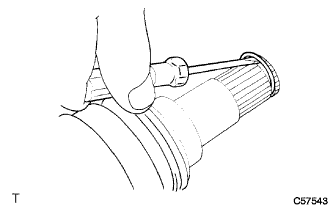
Using a screwdriver, remove the front drive shaft hole snap ring LH.
-
-
REMOVE FRONT DRIVE SHAFT ASSEMBLY RH
-
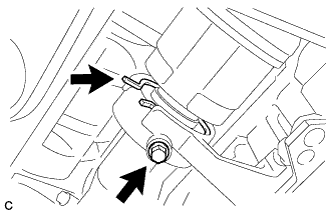
Separate the bearing bracket hole snap ring from the drive shaft bearing bracket.
-
Remove the bolt and front drive shaft assembly RH from the drive shaft bearing bracket.
Note
-
Do not damage the front transaxle case oil seal.
-
Do not damage the front axle inboard joint boot.
-
Do not drop the front drive shaft assembly RH.
-
-
Remove the bearing bracket hole snap ring from the front drive shaft assembly RH.
-
-
REMOVE FRONT FRAME ASSEMBLY
-
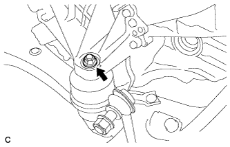
Remove the nut and separate the engine mounting insulator LH.
-
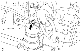
Remove the bolt and separate the front engine mounting insulator.
-
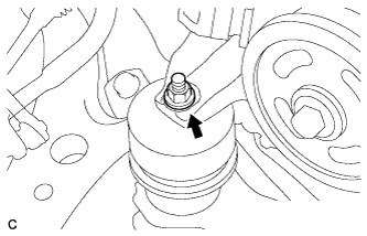
Remove the nut and separate the engine mounting insulator RH.
-
Remove the front frame assembly.
-
Using a height adjustable attachment and plate lift attachment, place the engine assembly on a flat level surface.
Note
-
Using a height adjustable attachment and plate lift attachment, place the engine assembly with transaxle horizontally.
-
To prevent the oil pan from deforming, do not place any attachments onto the oil pan of the engine assembly with transaxle.
-
Using an engine sling device and engine lift, secure the engine assembly before service.
-
-
-
REMOVE WIRING HARNESS CONNECTOR
-
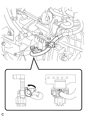
Disconnect the wire harness clamp.
-
Turn the lock lever and disconnect the connector from the wiring harness connector.
-
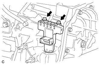
Remove the 2 bolts and wiring harness connector from the automatic transaxle assembly.
-
-
SEPARATE WIRE HARNESS
-
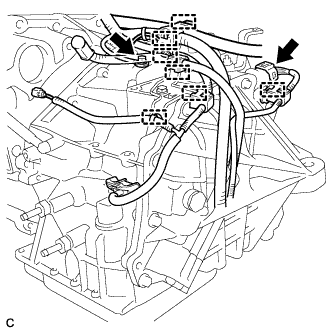
Remove the bolt and ground cable.
-
Separate the park/neutral position switch connector and 7 wire harness clamps.
-
-
REMOVE AUTOMATIC TRANSAXLE ASSEMBLY
-
Using the transmission jack attachment, set the automatic transaxle assembly on a transmission jack.
Note
-
Secure the automatic transaxle assembly to the transmission jack using a suitable adapter, such as a rope or attachment.
-
To prevent the oil pan from deforming, do not place any attachments onto the oil pan of the automatic transaxle assembly.
-
Hold the engine assembly with a suitable adapter, such as a rope, during the operation.
-
-
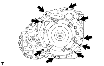
Remove the 9 bolts and automatic transaxle assembly.
Note
To prevent damage to the knock pins, do not pry between the automatic transaxle assembly and engine.
-
-
REMOVE TRANSMISSION OIL COOLER
-
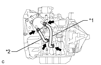
Text in Illustration *1 No. 1 Oil Cooler Inlet Hose *2 No. 1 Oil Cooler Outlet Hose Remove the No. 1 oil cooler inlet hose and No. 1 oil cooler outlet hose.
-
Remove the 3 bolts and transmission oil cooler from the front engine mounting bracket.
-
-
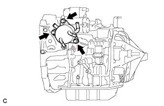
REMOVE FRONT ENGINE MOUNTING BRACKET
-
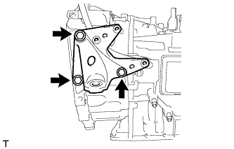
Remove the 3 bolts and front engine mounting bracket from the automatic transaxle assembly.
-
-
REMOVE NO. 1 TRANSMISSION CONTROL CABLE BRACKET
-
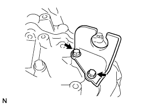
Remove the 2 bolts and No. 1 transmission control cable bracket from the automatic transaxle assembly.
-
-
REMOVE WIRE HARNESS CLAMP BRACKET
-
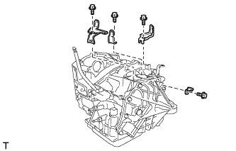
Remove the 4 bolts and 4 wire harness clamp brackets from the automatic transaxle assembly.
-
-
REMOVE TRANSMISSION CASE PLUG ASSEMBLY
-
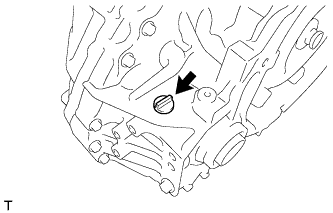
Remove the transmission case plug assembly from the automatic transaxle assembly.
-
Remove the O-ring from the transmission case plug assembly.
-
-
REMOVE TORQUE CONVERTER ASSEMBLY
-
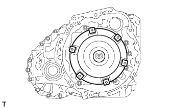
Remove the torque converter assembly from the automatic transaxle assembly.
-