ECD SYSTEM, Diagnostic DTC:32 (1)

| DTC Code | DTC Name |
|---|---|
| 32 (1) | Injection Pump System Malfunction |
DESCRIPTION
To compensate for the change in injection volume and injection timing caused by the variance in the injection pump itself, a correction is made by using the data that is stored in the ROM in the fuel pump correction unit.
| DTC No. | DTC Detection Condition | Trouble Area |
|---|---|---|
| 32 (1) |
|
|
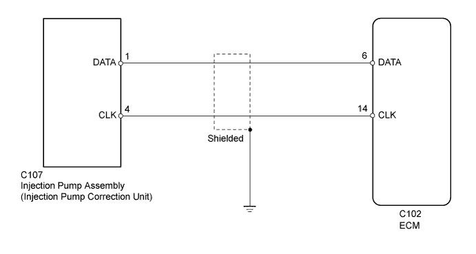
WIRING DIAGRAM
INSPECTION PROCEDURE
PROCEDURE
-
CHECK HARNESS AND CONNECTOR (ECM - INJECTION PUMP CORRECTION UNIT)
-
Disconnect the injection pump correction unit connector.
-
Disconnect the ECM connector.
-
Measure the resistance according to the value(s) in the table below.
Standard Resistance (Check for Open) Tester Connection Condition Specified Condition C107-1 (DATA) - C102-6 (DATA) Always Below 1 Ω C107-4 (CLK) - C102-14 (CLK) Always Below 1 Ω Standard Resistance (Check for Short) Tester Connection Condition Specified Condition C107-1 (DATA) or C102-6 (DATA) - Body ground Always 10 kΩ or higher C107-4 (CLK) or C102-14 (CLK) - Body ground Always 10 kΩ or higher -
Reconnect the injection pump correction unit connector.
-
Reconnect the ECM connector.
NG 
REPAIR OR REPLACE HARNESS OR CONNECTOR
OK 
-
-
REPLACE INJECTION PUMP ASSEMBLY
-
Replace the injection pump assembly Click here.
NEXT
-
-
CHECK DTC OUTPUT (CHECK IF DTC 32 (1) IS OUTPUT AGAIN)
-
Connect the intelligent tester to the DLC3.
-
Clear the DTC Click here.
-
Turn the ignition switch to ON and turn the tester on.
-
Enter the following menus: Powertrain / Engine and ECT / DTC.
-
Read the DTCs Click here.
Result Result Proceed to DTC 32 (1) output again A No DTC output B
B
SYSTEM OK
A 
REPLACE ECM Click here
-