DESCRIPTION
The ECM operates the spill control valve to control the fuel injection volume. The spill control valve is mounted on the injection pump. The spill control valve's solenoid valve opens and closes the injection pressure release port. During fuel injection, the spill control valve is on (closed). The ECM determines the basic fuel injection amount based on the engine speed and accelerator pedal position. Then the ECM uses several other correctional factors to determine the final fuel injection amount. After fuel injection has begun, the ECM ensures the final fuel injection amount by performing the following: 1) by counting the number of NE signals, and 2) by turning the spill control valve from on (closed) to off (open) (injection pressure release port is open).
| DTC No. | DTC Detection Condition | Trouble Area |
|---|---|---|
| 18 (5) | Open or short in the spill control valve circuit at 500 rpm or more. |
|
INSPECTION PROCEDURE
PROCEDURE
- Click here
INSPECT SPILL CONTROL VALVE
-
Inspect the spill control valve (Click here).
- OKClick here
- NGClick here
-
- Click here
CHECK ECM (SPV+ VOLTAGE)
-
Disconnect the spill control valve connector.
-
Turn the ignition switch to ON.
-
Measure the voltage according to the value(s) in the table below.
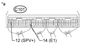
Standard Voltage Tester Connection Switch Condition Specified Condition C101-12 (SPV+) - C101-14 (E1) Ignition switch ON 11 to 14 V Table 1. Text in Illustration *a Component with harness connected
(ECM)
-
Reconnect the spill control valve connector.
- OKClick here
- NGClick here
-
- Click here
CHECK ECM (SPV- VOLTAGE)
-
Turn the ignition switch to ON.
-
Measure the voltage according to the value(s) in the table below.
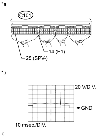
Standard Voltage Tester Connection Switch Condition Specified Condition C101-25 (SPV-) - C101-14 (E1) Ignition switch ON 11 to 14 V -
While idling, check the waveform with an oscilloscope connected between the specified terminals of the ECM connector.
OK Tester Connection Condition Specified Condition C101-25 (SPV-) - C101-14 (E1) Idling Correct waveform is as shown Table 2. Text in Illustration *a Component with harness connected
(ECM)
*b SPV- signal waveform
- OKClick here
- NGClick here
-
- Click here
CHECK HARNESS AND CONNECTOR (ECM - SPILL CONTROL VALVE)
-
Disconnect the spill control valve connector.
-
Disconnect the ECM connector.
-
Measure the resistance according to the value(s) in the table below.
Standard Resistance (Check for Open) Tester Connection Condition Specified Condition C106-2 - C101-12 (SPV+) Always Below 1 Ω C106-1 - C101-25 (SPV-) Always Below 1 Ω Standard Resistance (Check for Short) Tester Connection Condition Specified Condition C106-2 or C101-12 (SPV+) - Body ground Always 10 kΩ or higher C106-1 or C101-25 (SPV-) - Body ground Always 10 kΩ or higher -
Reconnect the spill control valve connector.
-
Reconnect the ECM connector.
- OKClick here
- NGClick here
-
- Click here
REPLACE INJECTION PUMP ASSEMBLYClick here
- Click here
REPLACE ECMClick here
- Click here
CHECK FOR INTERMITTENT PROBLEMSClick here
- Click here
REPAIR OR REPLACE HARNESS OR CONNECTOR
- Click here
REPLACE ECMClick here