ECD SYSTEM (w/o DPF), Diagnostic DTC:P1238

| DTC Code | DTC Name |
|---|---|
| P1238 | Injector Malfunction |
DESCRIPTION
Tech Tips
-
For more information on the injector assemblies and common rail system, refer to System Description Click here.
-
If DTC P1238 has been stored, refer to Diagnostic Trouble Code Chart Click here.
The ECM detects combustion deterioration for a specific cylinder.
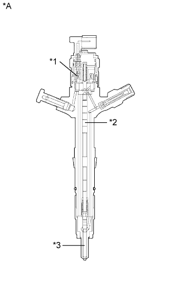
| *A | Injector Cross Section Diagram | - | - |
| *1 | Solenoid Valve | *2 | Piston |
| *3 | Nozzle Needle | - | - |
Tech Tips
-
The cylinder which has the compensation value, indicated by Injection Feedback Val #1, #2, #3 and #4, that varies from the other cylinders may be malfunctioning.
-
If DTC P0093 (fuel leaks from high-pressure area) is stored simultaneously, a leakage malfunction of a specific cylinder has probably occurred.
-
If DTC P0200 (open or short in the injector driver or injector circuit) is stored simultaneously, there is probably a faulty circuit located between the ECM and the injector assembly including the injector driver.
-
If only DTC P1238 (injector malfunction) has been stored, an injector assembly mechanical malfunction or insufficient compression (valve clearance, etc.) has probably occurred. An open or short malfunction of the ECM, injector driver or injector circuit is unlikely.
| DTC Detection Drive Pattern | DTC Detection Condition | Main Trouble Area | Related Trouble Area |
|---|---|---|---|
| Warm up the engine and idle it for 60 seconds | A large engine speed fluctuation when idling continues for 60 seconds (2 trip detection logic). |
|
|
| DTC No. | Data List |
|---|---|
| P1238 |
|
Tech Tips
-
If DTC P1238 is stored, the following symptoms may appear:
-
Rough idle
-
Poor driveability
-
After confirming DTC P1238, check the internal fuel pressure on the intelligent tester by entering the following menus: Powertrain / Engine and ECT / Data List / Fuel Press, Target Common Rail Pressure.
Under a stable condition such as idling or running the engine at 2500 rpm without load, Fuel Press is within 5000 kPa of Target Common Rail Pressure.
MONITOR DESCRIPTION
P1238 (Injection malfunction, except open or short in injector circuit):This DTC will be stored if the engine speed fluctuation between each cylinder is large. The ECM monitors changes in the crankshaft rotation speed using the crankshaft position sensor in order to detect improper combustion. The camshaft position sensor also plays a role in determining which cylinder has the problem. The fluctuation counter increases when irregular crankshaft rotation speed variation exceeds the threshold with the engine idling. Therefore, if any one of the cylinders is operating poorly (rough idle), the ECM stores this DTC.
WIRING DIAGRAM
Refer to DTC P0200 Click here.
INSPECTION PROCEDURE
Note
-
After replacing the ECM, the new ECM needs registration Click here and initialization Click here.
-
After replacing an injector assembly, the ECM needs registration Click here.
Tech Tips
-
Read freeze frame data using the intelligent tester. Freeze frame data records the engine condition when malfunctions are detected. When troubleshooting, freeze frame data can help determine if the vehicle was moving or stationary, if the engine was warmed up or not, and other data from the time the malfunction occurred.
-
When this DTC is stored, be sure to carefully examine "Injection Feedback Val #1 to #4", "Injection Volume", "Fuel Press", "Target Common Rail Pressure", "Engine Speed", "MAF", "Coolant Temp" and "Vehicle Speed" in the freeze frame data.
PROCEDURE
-
CHECK FOR ANY OTHER DTCS OUTPUT (IN ADDITION TO DTC P1238)
-
Connect the intelligent tester to the DLC3.
-
Turn the ignition switch to ON and turn the tester on.
-
Enter the following menus: Powertrain / Engine and ECT / DTC.
-
Read the DTCs.
Result Result Proceed to P1238 is output A P1238 and other DTCs are output B Tech Tips
-
If any DTCs other than P1238 are output, troubleshoot those DTCs first.
-
If DTCs other than P1238 are not output, check the fuel condition before proceeding to the next step.
-
B 
GO TO DTC CHART Click here
A 
-
-
CHECK HARNESS AND CONNECTOR (ENGINE WIRE HARNESS)
-
Check the wire harness and connector connections.
OK The wire harness and connectors have been connected securely and there are good connections.
NG 
REPAIR OR REPLACE HARNESS OR CONNECTOR Click here
OK
-
-
CHECK INJECTOR COMPENSATION CODE
-
Read the injector compensation codes Click here.
OK Compensation codes stored in the ECM match compensation codes of the installed injector assemblies.
NG
REGISTER INJECTOR COMPENSATION CODE AND PERFORM PILOT QUANTITY LEARNING Click here
OK
-
-
READ VALUE USING INTELLIGENT TESTER (COMPENSATORY INJECTION VOLUME FOR EACH CYLINDER)
-
Connect the intelligent tester to the DLC3.
-
Turn the ignition switch to ON and turn the tester on.
-
Enter the following menus: Powertrain / Engine and ECT / Data List / Injection Feedback Val #1 to #4.
-
Read the value.
Standard Value The compensatory injection volume is less than 3.0 mm3/st Tech Tips
-
If the fuel injector assembly is malfunctioning, the compensatory injection volume remains at 5.0 mm3/st.
-
If there is a disconnection, the feedback value will increase and +5.0 mm3/st will be indicated, because it will become impossible for the injector assembly to inject.
-
-
Inspect and repair the cylinder that has an improper compensation value according to the following steps.
NEXT
-
-
PERFORM ACTIVE TEST USING INTELLIGENT TESTER (CONTROL THE CYLINDER #1 TO #4 FUEL CUT)
-
Connect the intelligent tester to the DLC3.
-
Start the engine and turn the tester on.
-
Enter the following menus: Powertrain / Engine and ECT / Active Test / Control the Cylinder #1 to #4 Fuel Cut.
-
Check the 4 cylinders in sequence to identify any faulty cylinders by performing the power-balance inspection.
Tech Tips
-
If the engine idle speed does not change when an injector assembly is disabled, the cylinder being tested is malfunctioning.
-
If the cylinder being tested is normal, there will be a significant change in idle speed when the fuel injection is stopped for that cylinder.
-
NEXT
-
-
CHECK CYLINDER COMPRESSION PRESSURE OF MALFUNCTIONING CYLINDER
Tech Tips
Measure the compression of the cylinder that had a high speed during the "Check the Cylinder Compression" Active Test.
-
Check the cylinder compression pressure Click here.
NG
CHECK ENGINE TO DETERMINE CAUSE OF LOW COMPRESSION Click here
OK
-
-
REPLACE INJECTOR ASSEMBLY
-
Replace the injector assembly Click here.
NEXT
-
-
BLEED AIR FROM FUEL SYSTEM
-
Bleed the air from the fuel system Click here.
NEXT
-
-
REGISTER INJECTOR COMPENSATION CODE AND PERFORM PILOT QUANTITY LEARNING
-
Register the injector compensation code Click here.
-
Perform the injector pilot quantity learning Click here.
NEXT
-
-
CHECK WHETHER DTC OUTPUT RECURS (DTC P1238)
-
Connect the intelligent tester to the DLC3.
-
Turn the ignition switch to ON and turn the tester on.
-
Clear the DTCs Click here.
-
Turn the ignition switch off for 30 seconds or more.
-
Start the engine.
-
Warm up the engine (engine coolant temperature is 70°C (158°F) or higher) and idle it for 60 seconds (the shift lever should be in neutral, and the A/C switch and all accessory switches should be off).
-
Enter the following menus: Powertrain / Engine and ECT / DTC.
-
Read the pending DTCs.
Tech Tips
-
If no pending DTCs are output, proceed to the next step to check "All Readiness".
-
Perform the following procedure using the tester to determine whether or not the DTC judgment has been carried out.
-
Enter the following menus: Powertrain / Engine and ECT / Utility / All Readiness.
-
Input DTC P1238.
-
Check the DTC judgment result.
Result Tester Display Result Proceed to Pending DTC P1238 is output A All Readiness ABNORMAL A NORMAL B Tech Tips
If STATUS is INCOMPLETE or UNKNOWN, increase the idling time.
-
B
END
A
-
-
REPLACE ECM
-
Replace the ECM Click here.
NEXT
CONFIRM WHETHER MALFUNCTION HAS BEEN SUCCESSFULLY REPAIRED Click here
-
-
CHECK ENGINE TO DETERMINE CAUSE OF LOW COMPRESSION
NEXT
CONFIRM WHETHER MALFUNCTION HAS BEEN SUCCESSFULLY REPAIRED Click here
-
REPAIR OR REPLACE HARNESS OR CONNECTOR
-
Repair or replace the harness or connector.
NEXT
-
-
CONFIRM WHETHER MALFUNCTION HAS BEEN SUCCESSFULLY REPAIRED
-
Connect the intelligent tester to the DLC3.
-
Clear the DTCs Click here.
-
Turn the ignition switch off for 30 seconds or more.
-
Start the engine.
-
Warm up the engine (engine coolant temperature is 70°C (158°F) or higher) and idle it for 60 seconds (the shift lever should be in neutral, and the A/C switch and all accessory switches should be off).
-
Confirm that the DTC is not output again.
Tech Tips
Perform the following procedure using the tester to determine whether or not the DTC judgment has been carried out.
-
Enter the following menus: Powertrain / Engine and ECT / Utility / All Readiness.
-
Input DTC P1238.
-
Check that STATUS is NORMAL. If STATUS is INCOMPLETE or UNKNOWN, increase the idling time.
-
NEXT 
END
-