ECD SYSTEM (w/o DPF), Diagnostic DTC:P0093

| DTC Code | DTC Name |
|---|---|
| P0093 | Fuel System Leak Detected - Large Leak |
DESCRIPTION
The fuel pressure sensor mounted on the common rail converts the fuel pressure inside the common rail into an electrical signal and outputs the signal to the ECM. The ECM controls the supply pump in order to maintain the fuel pressure inside the common rail at a target pressure calculated by the ECM. Refer to System Description Click here.
Tech Tips
-
If the drop in the internal fuel pressure is large when injecting fuel, the ECM interprets this as a fault and stores P0093.
-
If P0093 is present, refer to "Diagnostic Trouble Code (DTC) Table for Common Rail System" Click here.
| DTC Detection Drive Pattern | DTC Detection Condition | Trouble Area |
|---|---|---|
| After idling for 60 seconds, run engine at 2500 rpm for 30 seconds. Fully depress the accelerator pedal for 5 seconds, and then release it. (*A) Rev the engine to 3000 rpm and fully release the accelerator pedal immediately after the engine reaches 3000 rpm. (*B) Repeat procedures (*A) and (*B) 5 times. |
The fuel pressure decreases greatly when the engine is running. (1 trip detection logic) |
|
| DTC No. | Data List |
|---|---|
| P0093 |
|
Tech Tips
When DTC P0093 is set, check the internal fuel pressure of the common rail by entering the following menus on the intelligent tester: Powertrain / Engine / Data List / Fuel Press.
| Reference | ||||||
|---|---|---|---|---|---|---|
|
MONITOR DESCRIPTION
-
This DTC indicates that fuel leaks exist in high pressure areas in the common rail system. The ECM constantly monitors the internal fuel pressure of the common rail after the engine is started. The ECM stores this DTC if the drop in the internal fuel pressure is large when injecting fuel.
In the common rail system, high-pressure fuel is always supplied to the high-pressure areas including the fuel supply pump assembly, common rail assembly, injector assemblies and piping. The ECM adjusts the suction control valve opening angle to obtain the target internal fuel pressure.
If this DTC is stored, the ECM enters fail-safe mode. In fail-safe mode, both fuel injection and fuel supply pump assembly operation are suspended, and then the engine is stopped. Before the engine is stopped, the ECM permits the vehicle to be driven for 1 minute. The ECM continues operating in fail-safe mode until the ignition switch is turned off.
P0093 (Fuel leaks in high-pressure areas):
MONITOR STRATEGY
| Required sensors | Fuel pressure sensor |
| Frequency of operation | Continuous |
| Duration | 1 second |
| MIL operation | 1 driving cycle |
INSPECTION PROCEDURE
Note
-
Soon after starting the engine, visually check for fuel leaks in the fuel line.
-
After replacing the ECM, the new ECM needs registration Click here and initialization Click here.
-
After replacing the fuel supply pump assembly, the ECM needs initialization Click here.
-
After replacing an injector assembly, the ECM needs registration Click here.
Tech Tips
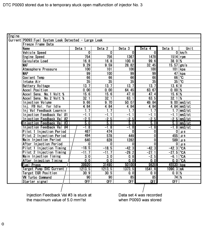
Read freeze frame data using the intelligent tester. Freeze frame data records the engine condition when malfunctions are detected. When troubleshooting, freeze frame data can help determine if the vehicle was moving or stationary, if the engine was warmed up or not, and other data from the time the malfunction occurred.
Tech Tips
-
The following can be deduced from the above freeze frame data:
-
The common rail fuel pressure dropped suddenly when the engine was being run at a moderate engine speed during engine warmup and DTC P0093 was stored at the point when data set 4 was recorded.
-
Injection Feedback Val #3 is 5.0 mm3/st which is large (the normal value is between -3.0 and 3.0 mm3/st) and indicates that the injector assembly of cylinder 3 may be malfunctioning.
-
Actual cause: In this case, foreign matter in the fuel is stuck inside an injector assembly causing the injector assembly to malfunction temporarily.
In order to remove the foreign matter in the fuel (the main cause of the problem), the fuel filter case needs to be cleaned and the fuel filter needs to be replaced.
Tech Tips
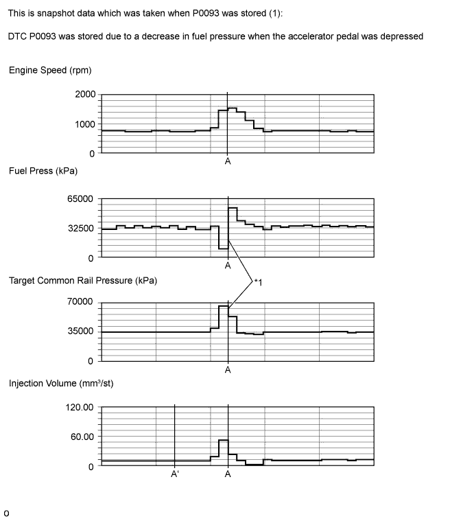
*1: Fuel press suddenly decreases for a moment, and then recovers. This can be seen clearly by comparing it to target common rail pressure.
Tech Tips
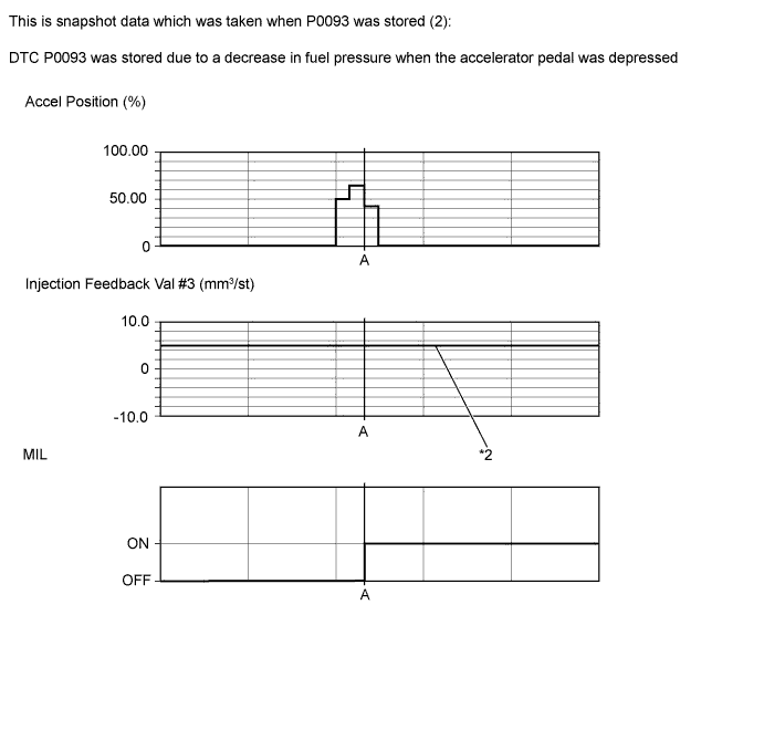
*2: Injection feedback Val #3 is 5.0 mm3/st which is large (the normal value is between -3.0 and 3.0 mm3/st) and indicates that the injector assembly of cylinder 3 may be malfunctioning.
| Data List | Value | Unit |
|---|---|---|
| Engine Speed | 1478 | rpm |
| Fuel Press | 8900 | kPa |
| Target Common Rail Pressure | 65320 | kPa |
| Injection Volume (Point A) | 51.26*1 | mm3/st |
| Injection Volume (Point A`) | 9.76 | mm3/st |
| Accel Position | 63.67 | % |
| Injection Feedback Val #1 | -1.1 | mm3/st |
| Injection Feedback Val #2 | -2.5 | mm3/st |
| Injection Feedback Val #3 | 5.0 | mm3/st |
| Injection Feedback Val #4 | -1.8 | mm3/st |
| MIL | ON | - |
PROCEDURE
-
CHECK FOR FUEL LEAKS (IN HIGH-PRESSURE AREAS)
-
Before starting the engine, visually check for fuel leaks from the fuel supply pump assembly, injector assembly, common rail assembly, and the fuel pipes in high-pressure areas.
OK No fuel leaks in high-pressure areas.
NG 
REPAIR FUEL LEAK POINT
OK 
-
-
CHECK FOR ANY OTHER DTCS OUTPUT (IN ADDITION TO DTC P0093) AND RECORD STORED DTC AND FREEZE FRAME DATA (PROCEDURE 2)
-
Connect the intelligent tester to the DLC3.
-
Turn the ignition switch to ON and turn the intelligent tester on.
-
Enter the following menus: Powertrain / Engine / DTC.
-
Read the DTCs and freeze frame data.
Result Result Proceed to P0093 and "P0190, P0192 and/or P0193" C P0093 and "P0335 and/or P0339" B Except above A
B
GO TO CRANKSHAFT POSITION SENSOR "A" CIRCUIT Click here
C
GO TO FUEL RAIL PRESSURE SENSOR CIRCUIT Click here
A
-
-
CHECK FUEL RECEIVER GAUGE (AMOUNT OF FUEL)
-
Check if the fuel level is low.
Result Result Proceed to The indicator (fuel warning light) is illuminated A The indicator (fuel warning light) is not illuminated B
B 
CHECK FREEZE FRAME DATA (INJECTION FEEDBACK VAL #1 TO #4) Click here
A
-
-
ADD FUEL
-
Add fuel.
NEXT
-
-
CHECK WHETHER DTC OUTPUT RECURS (DTC P0093)
-
Using the hand pump mounted on the fuel filter cap, bleed the air from the fuel system. Continue pumping until the pump resistance increases.
Note
-
Hand pump pumping speed: Max. 2 strokes/sec.
-
The hand pump must be pushed with a full stroke during pumping.
-
When the fuel pressure at the supply pump inlet port reaches a saturated pressure, the hand pump resistance increases.
-
If pumping is interrupted during the air bleeding process, fuel in the fuel line may return to the fuel tank. Continue pumping until the hand pump resistance increases.
-
If the hand pump resistance does not increase despite consecutively pumping 200 times or more, there may be a fuel leak between the fuel tank and fuel filter element sub-assembly, the hand pump may be malfunctioning, or the vehicle may have run out of fuel.
-
If a large amount of air remains inside the fuel system, the common rail pressure does not rise to the pressure range necessary for normal use, and the engine cannot be started.
-
-
Start the engine.
Note
-
If a large amount of air remains inside the fuel system, the starter may need to be cranked for 10 seconds or more to start the engine.
-
Do not crank the engine continuously for more than 20 seconds. The battery may be discharged.
-
Use a fully-charged battery.
-
When the engine can be started, proceed to the next step.
-
If the engine cannot be started, bleed the air again using the hand pump until the hand pump resistance increases. Then start the engine.
-
-
Turn the ignition switch off.
-
Connect the intelligent tester to the DLC3.
-
Turn the ignition switch to ON and turn the intelligent tester on.
-
Clear DTCs Click here.
-
Start the engine. (*A)
-
Enter the following menus: Powertrain / Engine / Active Test / Test the Fuel Leak. (*B)
-
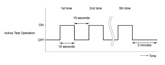
Perform the following test 5 times with on/off intervals of 10 seconds: Active Test / Test the Fuel Leak. (*C)
-
Allow the engine to idle for 3 minutes or more after performing the Active Test for the fifth time. (*D)
-
Enter the following menus: Powertrain / Engine / DTC.
-
Read Current DTCs.
-
When no DTCs are output, the air bleeding is completed.
-
If any DTCs are output, proceed to the next step.
-
-
Repeat steps (*A) to (*D).
-
Clear DTCs Click here.
-
Start the engine and warm it up.
-
Confirm that the shift lever is in neutral and securely apply the parking brake.
-
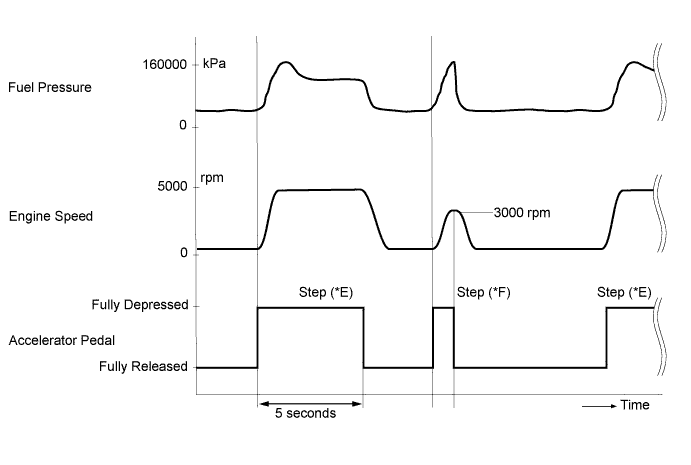
Fully depress the accelerator pedal for 5 seconds, and then release it. (*E)
-
Rev the engine to 3000 rpm and fully release the accelerator pedal immediately after the engine reaches 3000 rpm. (*F)
-
Repeat procedures (*E) and (*F) 5 times.
-
Enter the following menus: Powertrain / Engine / DTC.
-
Read Current DTCs.
Result Result Proceed to DTC output A DTC not output B
B
DTC CAUSED BY RUNNING OUT OF FUEL
A
-
-
CHECK FREEZE FRAME DATA (INJECTION FEEDBACK VAL #1 TO #4)
-
Read the value of Injection Feedback Val #1 to #4 in the freeze frame data recorded in Procedure 2.
Result Result Proceed to Injection Feedback Val for at least one cylinder is 5 mm3/st in at least 1 set of freeze frame data
B Except above A Tech Tips
When there is a problem with the operation of an injector assembly due to foreign matter in the inside of the injector assembly, etc., the fuel injection volume decreases. As a result, the ECM gives instructions to increase the fuel injection volume, which causes Injection Feedback Val to increase.
B
REPLACE FUEL FILTER ELEMENT SUB-ASSEMBLY Click here
A
-
-
READ VALUE USING INTELLIGENT TESTER (FUEL PRESS)
-
Connect the intelligent tester to the DLC3.
-
Turn the ignition switch to ON and turn the tester on.
-
Clear the DTCs Click here.
-
Enter the following menus: Powertrain / Engine and ECT / Data List / Fuel Press.
-
Start the engine.
-
Read the value of Fuel Press while cranking and idling the engine.
Result Result Proceed to The engine cannot be started or the engine can be started but Fuel Press is below 20000 kPa 2 seconds after the starter signal changes from OFF to ON B Except above A
B
REPLACE INJECTOR ASSEMBLIES OF ALL CYLINDERS Click here
A
-
-
READ VALUE USING INTELLIGENT TESTER (INJECTION FEEDBACK VAL #1 TO #4)
-
Connect the intelligent tester to the DLC3.
-
Turn the ignition switch to ON and turn the tester on.
-
Start the engine and warm it up.
-
Enter the following menus: Powertrain / Engine and ECT / Data List / Injection Feedback Val #1 to #4.
-
Read the values.
Standard Tester Display Engine Condition* Normal Value Injection Feedback Val #1
Injection Feedback Val #2
Injection Feedback Val #3
Injection Feedback Val #4
Idling -3.0 mm3/st to 3.0 mm3/st
Tech Tips
*: The A/C switch and all accessory switches should be off, the engine coolant temperature should be 70°C (158°F) or higher and the engine should be idled for 1 minute or more.
Result Result Proceed to Injection Feedback Val for at least one cylinder is more than 3 mm3/st and engine vibration is abnormally large
B Except above A Tech Tips
-
When there is a problem with the operation of an injector assembly due to foreign matter in the inside of the injector assembly, etc., the fuel injection volume decreases. As a result, the ECM gives instructions to increase the fuel injection volume, which causes Injection Feedback Val to increase.
-
The ECM controls the system so that the sum of Injection Feedback Val for all of the cylinders is approximately 0 mm3/st. Even if the value of Injection Feedback Val for a cylinder is less than -3.0 mm3/st (-3.0 mm3/st is the lowest normal value), as long as the value of Injection Feedback Val for each of the other cylinders is 3.0 mm3/st or less, the injector assemblies are not malfunctioning.
-
B
REPLACE FUEL FILTER ELEMENT SUB-ASSEMBLY Click here
A
-
-
CHECK ENGINE SPEED
-
Start the engine and drive the vehicle until the engine coolant temperature reaches 60°C (140°F) or higher.
-
Stop the vehicle and allow the engine to idle.
-
While checking the tachometer, fully depress the accelerator pedal for 5 seconds, and then release it.*1
-
Repeat procedure *1 5 times.
Result Result Proceed to No problems such as sluggishness or variations in the tachometer reading A Except above B
B
READ VALUE USING INTELLIGENT TESTER (ENGINE SPEED) Click here
A
-
-
REPLACE FUEL FILTER ELEMENT SUB-ASSEMBLY
-
Replace the fuel filter element sub-assembly.
NEXT
-
-
BLEED AIR FROM FUEL SYSTEM
-
Bleed the air from the fuel system Click here.
NEXT
-
-
PERFORM ACTIVE TEST USING INTELLIGENT TESTER (TEST THE FUEL LEAK)
-
Connect the intelligent tester to the DLC3.
-
Turn the ignition switch to ON and turn the tester on.
-
Enter the following menus: Powertrain / Engine / Active Test / Test the Fuel Leak / Data List / Fuel Press, Target Common Rail Pressure, and Target Pump SCV Current.
-
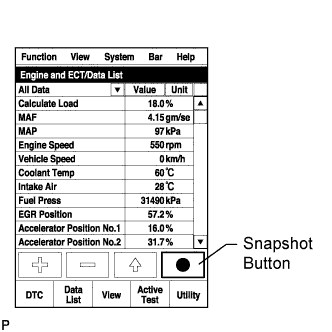
Take a snapshot with the intelligent tester during the Active Test.
Tech Tips
Detailed graphs can be displayed by transferring the stored snapshot from the tester to a PC (personal computer) with Intelligent Viewer installed.
-
Measure the difference between the target fuel pressure (Target Common Rail Pressure) and the actual fuel pressure (Fuel Press) when the "Test the Fuel Leak" Active Test is performed Click here.
Tech Tips
In order to obtain an exact measurement, perform the Active Test 5 times and measure the difference once each time the Active Test is performed.
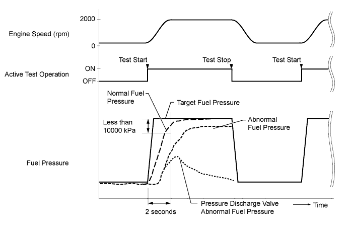
OK The difference between the target fuel pressure and the actual fuel pressure 2 seconds after the Active Test starts is less than 10000 kPa. Tech Tips
-
"Target Common Rail Pressure" is the target fuel pressure controlled by the ECM.
-
"Fuel Press" is the actual fuel pressure.
Result Result Proceed to The difference between the target fuel pressure and the actual fuel pressure 2 seconds after the Active Test starts is less than 10000 kPa A Except above B -
B
REPLACE INJECTOR ASSEMBLIES OF ALL CYLINDERS Click here
A
-
-
PERFORM ACTIVE TEST USING INTELLIGENT TESTER (CONTROL THE CYLINDER #1 TO #4 FUEL CUT)
Tech Tips
Use this Active Test to determine the malfunctioning cylinder.
-
Connect the intelligent tester to the DLC3.
-
Start the engine and turn the tester on.
-
Enter the following menus: Powertrain / Engine and ECT / Active Test / Control the Cylinder #1 to #4 Fuel Cut.
Tech Tips
-
If the engine idle speed does not change when an injector assembly is disabled, the cylinder being tested is malfunctioning. Record any malfunctioning cylinders.
-
If the cylinder being tested is normal, there will be a significant change in idle speed when the fuel injection is stopped for that cylinder.
-
NEXT
-
-
REPLACE INJECTOR ASSEMBLY OF MALFUNCTIONING CYLINDER
-
Replace the injector assembly of the malfunctioning cylinder Click here.
NEXT
BLEED AIR FROM FUEL SYSTEM Click here
-
-
REPLACE INJECTOR ASSEMBLIES OF ALL CYLINDERS
-
Replace the injector assemblies Click here.
NEXT
-
-
BLEED AIR FROM FUEL SYSTEM
-
Bleed the air from the fuel system Click here.
NEXT
-
-
REGISTER INJECTOR COMPENSATION CODE AND PERFORM PILOT QUANTITY LEARNING
-
Register the injector compensation code Click here.
-
Perform the injector pilot quantity learning Click here.
NEXT
CHECK WHETHER DTC OUTPUT RECURS (DTC P0093) Click here
-
-
READ VALUE USING INTELLIGENT TESTER (ENGINE SPEED)
-
Connect the intelligent tester to the DLC3.
-
Turn the ignition switch to ON and turn the tester on.
-
Enter the following menus: Powertrain / Engine / Data List / Engine Speed.
-
Read the value while cranking and idling the engine.
Standard Tester Display Engine Condition Specified Condition Engine Speed Cranking 50 to 400 rpm Idling with warm engine 650 to 750 rpm Tech Tips
The value should be the same as the actual engine speed and displayed with no interruption on the tester.
NG
REPLACE CRANKSHAFT POSITION SENSOR Click here
OK
-
-
INSPECT ECM (FUEL PRESSURE SENSOR OUTPUT VOLTAGE)
-
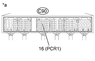
Text in Illustration *a Component with harness connected
(ECM)
Connect the positive (+) probe of an oscilloscope to the fuel pressure sensor input terminal of the ECM connector and the negative (-) probe to the body ground.
-
Turn the ignition switch to ON.
-
Check for any noise in the waveform when vibration is applied to the wire harness and connectors between the fuel pressure sensor and ECM.
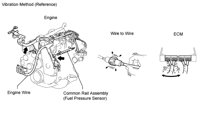
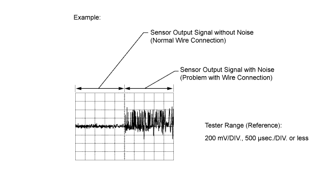
Standard Voltage Tester Connection Condition Specified Condition C90-16 (PCR1) - Body ground Vibration is applied to the wire harness and connectors No noise in the waveform Result Result Proceed to MIL comes on or noise present in the waveform B Except above A
B
REPAIR OR REPLACE HARNESS OR CONNECTOR (ECM - FUEL PRESSURE SENSOR) Click here
A
-
-
INSPECT FUEL TEMPERATURE SENSOR (SENSOR OUTPUT)
-
Connect the intelligent tester to the DLC3.
-
Turn the ignition switch to ON and turn the tester on.
-
Enter the following menus: Powertrain / Engine / Data List / Fuel Temperature.
-
Read the value.
OK The value is almost the same as the actual fuel temperature. Tech Tips
-
When the engine is stopped and left overnight, the fuel temperature becomes the same as the ambient temperature.
-
If there is a problem with the fuel temperature sensor, and a fuel temperature value lower than the actual fuel temperature is indicated, P0093 may be stored.
-
NG
REPLACE FUEL TEMPERATURE SENSOR Click here
OK
-
-
CHECK FOR INTERMITTENT PROBLEMS
-
Check for intermittent problems Click here.
NEXT
CHECK WHETHER DTC OUTPUT RECURS (DTC P0093) Click here
-
-
REPLACE CRANKSHAFT POSITION SENSOR
-
Replace the crankshaft position sensor Click here.
Tech Tips
Before replacing the crankshaft position sensor, perform a wire harness inspection and if there are any problems with the wire harness, repair or replace it.
NEXT
CHECK WHETHER DTC OUTPUT RECURS (DTC P0093) Click here
-
-
REPAIR OR REPLACE HARNESS OR CONNECTOR (ECM - FUEL PRESSURE SENSOR)
-
Repair or replace the harness or connector.
NEXT
-
-
INSPECT ECM (FUEL PRESSURE SENSOR OUTPUT VOLTAGE)
-
Text in Illustration *a Component with harness connected
(ECM)
Connect the positive (+) probe of an oscilloscope to the fuel pressure sensor input terminal of the ECM connector and the negative (-) probe to the body ground.
-
Turn the ignition switch to ON.
-
Check for any noise in the waveform when vibration is applied to the wire harness and connectors between the fuel pressure sensor and ECM.
Standard Voltage Tester Connection Condition Specified Condition C90-16 (PCR1) - Body ground Vibration is applied to the wire harness and connectors No noise in the waveform Result Result Proceed to MIL comes on or noise present in the waveform A Except above B
B
CHECK WHETHER DTC OUTPUT RECURS (DTC P0093) Click here
A
-
-
REPLACE COMMON RAIL ASSEMBLY
-
Replace the common rail assembly Click here.
Tech Tips
Before replacing the common rail assembly, perform a wire harness inspection and if there are any problems with the wire harness, repair or replace it.
NEXT
-
-
BLEED AIR FROM FUEL SYSTEM
-
Bleed the air from the fuel system Click here.
NEXT
CHECK WHETHER DTC OUTPUT RECURS (DTC P0093) Click here
-
-
REPLACE FUEL TEMPERATURE SENSOR
-
Replace the fuel temperature sensor.
Tech Tips
Before replacing the fuel temperature sensor, perform a wire harness inspection and if there are any problems with the wire harness, repair or replace it.
NEXT
-
-
CHECK WHETHER DTC OUTPUT RECURS (DTC P0093)
-
Connect the intelligent tester to the DLC3.
-
Turn the ignition switch to ON and turn the tester on.
-
Enter the following menus: Powertrain / Engine / DTC.
-
Clear DTCs Click here.
-
Start the engine.
-
Warm up the engine (engine coolant temperature is 70°C (158°F) or higher).
-
Confirm that the shift lever is in neutral and securely apply the parking brake.
-
Fully depress the accelerator pedal for 5 seconds, and then release it. (*A)
-
Rev the engine to 3000 rpm and fully release the accelerator pedal immediately after the engine reaches 3000 rpm. (*B)
-
Repeat procedures (*A) and (*B) 5 times.

-
Enter the following menus: Powertrain / Engine / DTC.
-
Read the DTCs.
OK No DTCs are output.
NEXT 
END
-