| DTC Code | DTC Name |
|---|---|
| P0046 | Turbocharger / Supercharger Boost Control Solenoid Circuit Range / Performance |
| P0047 | Turbocharger/Supercharger Boost Control "A" Circuit Low |
| P0048 | Turbocharger/Supercharger Boost Control "A" Circuit High |
DESCRIPTION
These DTCs indicate that the DC motor of the turbocharger is malfunctioning. The ECM monitors the DC motor current to detect an open or short in the DC motor circuit. If the current meets certain criteria, the ECM stores a DTC and illuminates the MIL immediately.
The DC motor is used to operate the nozzle vane of the turbocharger. The nozzle vane opens and closes to change the velocity of exhaust emissions in order to control the turbo pressure. The ECM varies the duty ratio of the DC motor in accordance with the driving conditions.
If the nozzle vane is stuck closed (DC motor stuck off), drivability may deteriorate at wide open throttle. If the nozzle vane is stuck open (DC motor stuck on), drivability may deteriorate at intermediate throttle positions or the engine power may be insufficient.
| DTC Detection Drive Pattern | DTC Detection Condition | Trouble Area |
|---|---|---|
| Ignition switch ON for 5 seconds | Either condition is met when the motor is operating (1 trip detection logic):
|
|
| DTC Detection Drive Pattern | DTC Detection Condition | Trouble Area |
|---|---|---|
| 2 seconds after engine is started, race engine for 1 second | Both conditions are met for 1 second or more when the motor is operating (1 trip detection logic):
|
|
| DTC Detection Drive Pattern | DTC Detection Condition | Trouble Area |
|---|---|---|
| 2 seconds after engine is started, race engine for 1 second | Overcurrent is detected 25 times or more (1 trip detection logic). |
|
-
If DTC P0046, P0047 and/or P0048 is stored due to the nozzle vane being stuck closed, the following symptom may appear:
-
-
Vehicle surge when driving with full load
-
-
If DTC P0046, P0047 and/or P0048 is stored due to the nozzle vane being stuck open, the following symptoms may appear:
-
-
Lack of power
-
Vehicle surge or hesitation under light or medium load
-
INSPECTION PROCEDURE
Read freeze frame data using the intelligent tester. Freeze frame data records the engine condition when malfunctions are detected. When troubleshooting, freeze frame data can help determine if the vehicle was moving or stationary, if the engine was warmed up or not, and other data from the time the malfunction occurred.
PROCEDURE
- Click here
CHECK FOR ANY OTHER DTCS OUTPUT (IN ADDITION TO DTC P0046, P0047 AND/OR P0048)
-
Connect the intelligent tester to the DLC3.
-
Turn the ignition switch to ON and turn the tester on.
-
Enter the following menus: Powertrain / Engine and ECT / DTC.
-
Read the DTCs.
Table 4. Result Result Proceed to P0046, P0047 and/or P0048 is output A P0046, P0047 and/or P0048 and other DTCs are output B Tip:If codes other than P0046, P0047 and/or P0048 are output, perform troubleshooting for those DTCs first.
-
- Click here
INSPECT TURBOCHARGER SUB-ASSEMBLY (DC MOTOR OPERATION)
-
Inspect the turbocharger sub-assembly (Click here).
- OKClick here
- NGClick here
-
- Click here
INSPECT TURBOCHARGER SUB-ASSEMBLY (DC MOTOR RESISTANCE)
-
Disconnect the DC motor connector.
-
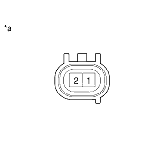
Measure the resistance according to the value(s) in the table below.
Standard Resistance Tester Connection Condition Specified Condition 1 (M-) - 2 (M+) Always 1 to 100 Ω Table 5. Text in Illustration *a Component without harness connected
(DC Motor)
-
Reconnect the DC motor connector.
- OKClick here
- NGClick here
-
- Click here
CHECK HARNESS AND CONNECTOR (DC MOTOR - ECM)
-
Disconnect the DC motor connector.
-
Disconnect the ECM connector.
-
Measure the resistance according to the value(s) in the table below.
Standard Resistance (Check for Open) Tester Connection Condition Specified Condition C75-1 (M-) - C93-7 (M-) Always Below 1 Ω C75-2 (M+) - C93-6 (M+) Always Below 1 Ω Standard Resistance (Check for Short) Tester Connection Condition Specified Condition C75-1 (M-) or C93-7 (M-) - Body ground Always 10 kΩ or higher C75-2 (M+) or C93-6 (M+) - Body ground Always 10 kΩ or higher -
Reconnect the DC motor connector.
-
Reconnect the ECM connector.
- OKClick here
- NGClick here
-
- Click here
REPLACE ECM
-
Replace the ECM (Click here).
- NEXTClick here
-
- Click here
REPLACE TURBOCHARGER SUB-ASSEMBLY
-
Replace the turbocharger sub-assembly (Click here).
- NEXTClick here
-
- Click here
REPAIR OR REPLACE HARNESS OR CONNECTOR
-
Repair or replace the harness or connector.
- NEXTClick here
-
- Click here
CONFIRM WHETHER MALFUNCTION HAS BEEN SUCCESSFULLY REPAIRED
-
Connect the intelligent tester to the DLC3.
-
Clear the DTCs (Click here).
-
Turn the ignition switch off.
-
Turn the ignition switch to ON for 5 seconds or more.
-
Enter the following menus: Powertrain / Engine / DTC.
-
Confirm that the DTC is not output again.
- NEXTClick here
-
- Click here
END
- Click here
CHECK FOR INTERMITTENT PROBLEMS
- Click here
GO TO DTC CHARTClick here