ECD SYSTEM (w/ DPF) DATA LIST / ACTIVE TEST

-
DATA LIST
Tech Tips
Using the intelligent tester to read the Data List allows the values or states of switches, sensors, actuators and other items to be read without removing any parts. This non-intrusive inspection can be very useful because intermittent conditions or signals may be discovered before parts or wiring is disturbed. Reading the Data List information early in troubleshooting is one way to save diagnostic time.
Note
In the table below, the values listed under "Normal Condition" are reference values. Do not depend solely on these reference values when deciding whether a part is faulty or not.
-
Warm up the engine.
-
Turn the engine switch off.
-
Connect the intelligent tester to the DLC3.
-
Turn the engine switch on (IG).
-
Start the engine.
-
Turn the intelligent tester on.
-
Enter the following menus: Powertrain / Engine and ECT / Data List.
Tech Tips
-
To display the list box, press the pull down menu button next to "Primary". Then select a measurement group.
-
When you select a measurement group, the ECU data belonging to that group is displayed.
-
Measurement Group List / Description
-
All Data / All data
-
Primary / -
-
Engine Control / Engine control system related data
-
Vehicle Information / Vehicle information
-
Monitor Status / Monitor status related data
-
AF Control System / Not Applicable
-
Catalytic Converter / Not Applicable
-
Evaporative / Not Applicable
-
A/T / Automatic transaxle system related data
-
ETCS / Not Applicable
-
Misfire / Not Applicable
-
Compression / Data used during "Check the Cylinder Compression" Active Test
-
HC Adsorber System / Not Applicable
-
Diesel Driving / Driving condition data
-
Diesel Injection / Fuel system related data
-
Diesel EGR / EGR system related data
-
Diesel Throttle / Diesel throttle system related data
-
Diesel VN Turbo / VN turbo related data
-
Diesel Exhaust / Exhaust system related data
-
Diesel Starting / "Difficult to start" related data
-
Diesel Rough / "Rough idle" related data
-
Diesel Power / "Lack of power" related data
-
-
Check the values by referring to the table below.
Tech Tips
"Result of real-vehicle check" is the assessment of one vehicle. Use it only for reference.
-
-
Engine Control
Calculate Load Tester Display Measurement Item/Range Normal Condition Type Cause of Out of Range Calculate Load Load calculated by ECM/
Min.: 0%, Max.: 100%
-
Idling: 7 to 26%
-
Running without load (2500 rpm): 10 to 20%
Calculated by ECM Malfunction in which turbo pressure or Mass Air Flow decreases Results of real-vehicle check:
-
Engine switch on (IG): 0%
-
Cranking: 58.4%
-
Idling (warm up the engine): 9.4% (2 minutes after starting the vehicle)
-
Running without load (2500 rpm): 19.6%
-
Running without load (4000 rpm): 29.4%
-
Driving with the accelerator fully open at 2000 rpm: 98%
-
Driving with the accelerator fully open at 3000 rpm: 98.2%
Diagnostic Note:
Calculated load = (Final injection volume / max. injection volume at current engine speed) x 100.
MAF Tester Display Measurement Item/Range Normal Condition Type Cause of Out of Range MAF Air flow rate from mass air flow meter/
Min.: 0 gm/s, Max.: 400 gm/s
-
Idling: 3 to 20 gm/s
-
Running without load (2000 rpm): 15 to 35 gm/s
Tech Tips
Depends on EGR rate
Sensor output (mass air flow meter)
-
Mass air flow meter
-
Mass air flow meter circuit
-
Intake related clog or leak
-
Exhaust related clog
-
Turbocharger sub-assembly
-
Leak or clog in passages for turbocharger
-
Malfunction in which EGR valve does not close
Results of real-vehicle check:
-
Engine switch on (IG): 0.39 gm/s
-
Cranking: 12.35 gm/s
-
Idling (warm up the engine): 4.39 gm/s (2 minutes after starting the vehicle)
-
Running without load (2500 rpm): 29.64 gm/s
-
Running without load (4000 rpm): 104.35 gm/s
-
Driving with the accelerator fully open at 2000 rpm: 106.42 gm/s
-
Driving with the accelerator fully open at 3000 rpm: 164.48 gm/s
Symptoms when out of range:
Rough idling
Diagnostic Note:
-
Based on the MAF, the ECM controls the fuel injection volume, injection timing, EGR, etc.
-
If the value is always approximately 0 gm/s:
-
Mass air flow meter power source circuit is open.
-
VG circuit is open or shorted.
-
EVG circuit is open.
Engine Speed Tester Display Measurement Item/Range Normal Condition Type Cause of Out of Range Engine Speed Engine speed/
Min.: 0 rpm, Max.: 6000 rpm
-
50 to 400 rpm: Cranking
-
650 to 750 rpm: Idling with warm engine
Sensor output (crankshaft position sensor)
-
Crankshaft position sensor
-
Crankshaft position sensor circuit
Symptoms when out of range:
-
Diagnostic Note:
When the crankshaft position sensor is malfunctioning, "Engine Speed" is approximately 0 or varies greatly from the actual engine speed.
Target Idle Engine Speed Tester Display Measurement Item/Range Normal Condition Type Cause of Out of Range Target Idle Engine Speed Target Idling Engine Speed/
Min.: 0 rpm, Max.: 10000 rpm
- Target idling speed (ECM calculated value) - Symptoms when out of range:
-
Diagnostic Note:
-
MAP Tester Display Measurement Item/Range Normal Condition Type Cause of Out of Range MAP Absolute pressure inside intake manifold/
Min.: 0 kPa, Max.: 255 kPa
-
Idling: 94 to 104 kPa (depends on barometric pressure and amount of EGR)
-
Engine running at 3000 rpm: 105 to 125 kPa
Sensor output (manifold absolute pressure sensor)
-
Manifold absolute pressure sensor
-
Intake related clog or leak
-
Exhaust related clog
-
Turbocharger sub-assembly
-
Leak or clog in passages for turbocharger
-
EGR valve stuck open
-
Exhaust leak
-
Throttle valve stuck closed
Results of real-vehicle check:
-
Engine switch on (IG): 100 kPa
-
Cranking: 99 kPa
-
Idling (warm up the engine): 96 kPa (2 minutes after starting the vehicle)
-
Running without load (2500 rpm): 101 kPa
-
Running without load (4000 rpm): 117 kPa
-
Driving with the accelerator fully open at 2000 rpm: 184 kPa
-
Driving with the accelerator fully open at 3000 rpm: 215 kPa
Symptoms when out of range:
Lack of power
Diagnostic Note:
-
When the engine switch is on (IG) or the vehicle is idling, the intake manifold absolute pressure and atmospheric pressure are approximately the same (standard atmospheric pressure = 101 kPa).
Above approximately 1500 rpm, the turbo becomes effective and the pressure becomes higher than atmospheric pressure.
-
Inspect while comparing with "Target Booster Pressure".
-
With the accelerator fully open, if the actual manifold absolute pressure (MAP) is low compared to the target booster pressure by at least 20 kPa for 5 seconds or more, a feeling of insufficient power will occur.
Vehicle Speed Tester Display Measurement Item/Range Normal Condition Type Cause of Out of Range Vehicle Speed Vehicle speed/
Min.: 0 km/h, Max.: 255 km/h
Actual vehicle speed Sensor output (speed sensor)
-
Speed sensor
-
Speed sensor circuit
Symptoms when out of range:
-
Diagnostic Note:
-
Coolant Temp Tester Display Measurement Item/Range Normal Condition Type Cause of Out of Range Coolant Temp Engine coolant temperature/
Min.: -40°C, Max.: 140°C
After warming up engine: 70 to 90°C (158 to 194°F) Sensor output (engine coolant temperature sensor)
-
Engine coolant temperature sensor
-
Thermostat
Symptoms when out of range:
Difficulty starting when engine is cold, rough idle, black smoke, lack of power
Diagnostic Note:
-
If the value is -40°C (-40°F) or 140°C (284°F), the sensor circuit is open or shorted.
-
After a long soak, the coolant temperature, intake air temperature and ambient temperature are approximately equal.
Intake Air Tester Display Measurement Item/Range Normal Condition Type Cause of Out of Range Intake Air Intake air temperature/
Min.: -40°C, Max.: 140°C
Equivalent to temperature at location of mass air flow meter Sensor output (intake air temperature sensor (built into mass air flow meter)) Intake air temperature sensor Symptoms when out of range:
-
Diagnostic Note:
-
After a long soak, the engine coolant temperature, intake air temperature and ambient temperature are approximately equal.
-
If the value is -40°C (-40°F) or 140°C (284°F), the sensor circuit is open or shorted.
Initial Engine Coolant Temp Tester Display Measurement Item/Range Normal Condition Type Cause of Out of Range Initial Engine Coolant Temp Initial engine coolant temperature/
Min.: -40°C, Max.: 120°C
Engine coolant temperature when engine started Sensor output when engine started - Diagnostic Note:
For freeze frame data, this tells whether the malfunction happened at a cold start or with a warm engine.
Initial Intake Air Temp Tester Display Measurement Item/Range Normal Condition Type Cause of Out of Range Initial Intake Air Temp Initial intake air temperature/
Min.: -40°C, Max.: 120°C
Intake air temperature when engine started Sensor output when engine started - Diagnostic Note:
-
Intake Air Temp (Turbo) Tester Display Measurement Item/Range Normal Condition Type Cause of Out of Range Intake Air Temp (Turbo) Intake air temperature after intercooler/
Min.: -40°C, Max.: 190°C
70°C (158°F) or less Sensor output (intake air temperature sensor after intercooler) Decreased cooling efficiency of intercooler (contamination, clogging) Diagnostic Note:
-
This is the intake air temperature at the intake manifold (after the intercooler).
-
During fail-safe operation, the value is set to 165°C (329°F). As the value is set to a high temperature, the turbo pressure may be suppressed and there may be a lack of power.
Glow Control Unit Duty Tester Display Measurement Item/Range Normal Condition Type Cause of Out of Range Glow Control Unit Duty Glow Control Unit Duty/
Min.: 0%, Max.: 127.5%
- Result of ECU calculations - Diagnostic Note:
This is the ECM command.
Eng Oil Press Switch Valve Tester Display Measurement Item/Range Normal Condition Type Cause of Out of Range Eng Oil Press Switch Valve Status of the Engine Oil Pressure Switching Valve/
ON or OFF
- Operation command - Diagnostic Note:
This is the ECM command.
"ON" means that the engine oil pressure is being maintained at a low pressure.
Engine Oil Pressure Tester Display Measurement Item/Range Normal Condition Type Cause of Out of Range Engine Oil Pressure Engine Oil Pressure value/
Min.: -2560 kPa, Max.: 2559.921 kPa
-
Idling (engine coolant temperature is 80°C (176°F) or less, A/C off and shift lever in neutral): 90 to 140 kPa
-
Engine running at 2500 rpm (engine coolant temperature is 80°C (176°F) or less, A/C off and shift lever in neutral): 140 to 195 kPa
-
Engine running at 3000 rpm (engine coolant temperature is 80°C (176°F) or less, A/C off and shift lever in neutral): 175 to 230 kPa
Tech Tips
-
The above values are valid for low pressure control mode when the engine coolant temperature is 75°C (167°F). The values change depending on the temperature.
-
When the engine coolant temperature is 80°C (176°F) or higher and the engine speed is 3000 rpm or more, the system changes to high pressure control mode.
Sensor output (oil pressure sender gauge assembly) - Diagnostic Note:
-
Alternate Duty Ratio Tester Display Measurement Item/Range Normal Condition Type Cause of Out of Range Alternate Duty Ratio Alternator generation duty ratio/
Min.: 0%, Max.: 100%
-
No electrical load at idling:
20 to 60%
-
High electrical load at idling:
100%
Duty value from ALT terminal
-
Battery deterioration
-
Alternator malfunction
-
Electric load, lights, etc.
Results of real-vehicle check:
Idling (no electrical load) (warm up the engine): 40% (2 minutes after starting the vehicle)
Symptoms when out of range:
-
Diagnostic Note:
-
This is outputs the alternator generation duty and is used to determine the electrical load.
-
Can be used to determine whether a higher-than-normal injection volume at idle, etc. is due to electrical loading or from some other source. For example, when the duty is not high but the idling injection volume is high, there is injector volume degradation or high engine friction.
-
Can be used for judging whether or not a malfunctioning component in the electrical system is generating continual generation requests (e.g., battery deterioration is causing an unending full recharge request, etc.). Regardless of whether or not an auxiliary device like the A/C or heater is active, if the alternator duty is always at the maximum value, there is an electrical system abnormality, like battery deterioration.
Starter Signal Tester Display Measurement Item/Range Normal Condition Type Cause of Out of Range Starter Signal Starter signal/
ON or OFF
ON: Cranking -
-
OFF malfunction (engine switch (STA) is ON but the signal is OFF and the starter is operating): Wire harness is open or shorted to ground
-
ON malfunction (engine switch (STA) is off but the signal is ON and the starter is not operating): Wire harness is shorted to +B
-
Operation malfunction: engine switch malfunction, starter relay malfunction, starter malfunction, battery or battery cable is defective, or wire harness is open or shorted
Symptoms when out of range:
-
Engine switch is on (IG) but the starter does not operate: Starting is not possible
-
Engine switch is off but the starter continues to operate: STA signal malfunction (P0617) is stored
Diagnostic Note:
Engine switch (STA) output:
-
ON: Starter is operating.
-
OFF: Starter is not operating.
Power Steering Signal Tester Display Measurement Item/Range Normal Condition Type Cause of Out of Range Power Steering Signal Power steering switch status/
ON or OFF
ON: Power steering operation Switch output (power steering switch)
-
OFF malfunction: Wire harness (power steering switch to ECM) is open or shorted to ground
-
ON malfunction: Wire harness (power steering switch to ECM) is shorted to +B
-
Power steering switch malfunction
Symptoms when out of range:
-
OFF malfunction (OFF during power steering operation): Engine speed decreases temporarily when power steering is operating
Diagnostic Note:
-
Power Steer. Sig. Record Tester Display Measurement Item/Range Normal Condition Type Cause of Out of Range Power Steer. Sig. Record Power steering switch status history/
ON or OFF
ON: When steering wheel first turned after engine switch on (IG) Power steering switch output history (after disconnecting and reconnecting the battery) - Diagnostic Note:
-
Power steering switch output history (after disconnecting and reconnecting the battery):
-
ON: Power steering operated in the past.
-
OFF: Power steering did not operate in the past.
A/C Signal Tester Display Measurement Item/Range Normal Condition Type Cause of Out of Range A/C Signal A/C (Air Conditioner) signal/
ON or OFF
ON: A/C on A/C operation signal output from A/C amplifier
-
ON: Operating
-
OFF: Not operating
-
A/C switch
-
A/C amplifier
-
A/C system malfunction, wire harness between A/C amplifier and ECU open or shorted
Symptoms when out of range:
OFF malfunction (OFF even when A/C switch is turned on):
-
Engine speed decreases temporarily when the A/C is operating.
Diagnostic Note:
-
Stop Light Switch Tester Display Measurement Item/Range Normal Condition Type Cause of Out of Range Stop Light Switch Stop light switch/
ON or OFF
-
ON: Brake pedal depressed
-
OFF: Brake pedal released
Switch output (stop light switch)
-
OFF malfunction: Wire harness (stop light switch to ECM, stop light switch to +B) open or shorted to ground
-
ON malfunction: Wire harness (stop light switch to ECM) shorted to +B
-
Stop light switch
Symptoms when out of range:
Stop light switch malfunction DTC P0504 is stored
Diagnostic Note:
Stop light switch (STP) operation condition:
-
ON: Light is on (Brake pedal is depressed).
-
OFF: Light is off (Brake pedal is released).
Immobiliser Communication Tester Display Measurement Item/Range Normal Condition Type Cause of Out of Range Immobiliser Communication Immobiliser communication/
ON or OFF
-
ON: Normal
-
OFF: Engine cannot be started due to immobiliser communication malfunction
-
-
Use of a non-registered key
-
Key battery is fully depleted
Symptoms when out of range:
-
Diagnostic Note:
-
Neutral Position SW Signal Tester Display Measurement Item/Range Normal Condition Type Cause of Out of Range Neutral Position SW Signal Neutral position switch status/
ON or OFF
ON: Shift lever in neutral Switch output (neutral position switch) - Symptoms when out of range:
-
Diagnostic Note:
-
Clutch Switch Tester Display Measurement Item/Range Normal Condition Type Cause of Out of Range Clutch Switch Clutch switch/
ON or OFF
ON: Clutch pedal depressed Switch output (Clutch switch assembly for cruise control system) - Symptoms when out of range:
The cruise control, pilot quantity learning, etc. may not function properly or may not function at all.
Diagnostic Note:
When this item displays "OFF" with the clutch pedal depressed, the shock when accelerating and decelerating the vehicle becomes larger and pilot quality learning cannot be performed.
Battery Voltage Tester Display Measurement Item/Range Normal Condition Type Cause of Out of Range Battery Voltage Battery voltage/
Min.: 0 V, Max.: 15 V
11 to 14 V - - Results of real-vehicle check:
-
Engine switch on (IG): 12.2 V
-
Cranking (with engine warmed up): 11.2 V
-
Idling (warm up the engine): 13.3 V
-
Running without load (2500 rpm): 13.6 V
-
Running without load (4000 rpm): 13.5 V
-
Driving with the accelerator fully open at 2000 rpm: 13.5 V
-
Driving with the accelerator fully open at 3000 rpm: 13.4 V
Symptoms when out of range:
If 5 V or less, starting becomes difficult
Diagnostic Note:
If 11 V or less, characteristics of some electrical components change.
Atmosphere Pressure Tester Display Measurement Item/Range Normal Condition Type Cause of Out of Range Atmosphere Pressure Atmospheric pressure value/
Min.: 50 kPa, Max.: 120 kPa
Actual atmospheric pressure Sensor output (atmospheric pressure sensor (built into ECM)) Atmospheric pressure sensor itself has failed (atmospheric pressure sensor is inside the ECM) Symptoms when out of range:
-
Diagnostic Note:
-
With the engine switch on (IG), when the difference between the atmospheric pressure sensor and intake manifold absolute pressure is 10 kPa or more, there is a malfunction in one of the sensors.
-
With the engine switch on (IG), when the atmospheric pressure is 0 kPa or 140 kPa, there is a malfunction in the sensor circuit.
-
Standard atmospheric pressure: 101 kPa.
-
For every 100 m increase in elevation, pressure drops by 1 kPa.
This varies by weather (high atmospheric pressure, low atmospheric pressure).
ACT VSV Tester Display Measurement Item/Range Normal Condition Type Cause of Out of Range ACT VSV A/C cut status for Active Test/
ON or OFF
- - - Diagnostic Note:
"Control the A/C Cut Signal" Active Test support data.
ACM Inhibit Tester Display Measurement Item/Range Normal Condition Type Cause of Out of Range ACM Inhibit VSV for engine mount status/
ON or OFF
- - - Diagnostic Note:
-
VSV for engine mount status:
-
Engine switch is on (IG): OFF.
-
Idling: ON.
-
"Control the ACM Inhibit" Active Test support data.
TC and TE1 Tester Display Measurement Item/Range Normal Condition Type Cause of Out of Range TC and TE1 TC and TE1 connection status for Active Test/
ON or OFF
- - - Diagnostic Note:
When the "Connect the TC and TE1" Active Test is performed, the system behaves as if TC and CG were connected.
# Codes (Include History) Tester Display Measurement Item/Range Normal Condition Type Cause of Out of Range # Codes (Include History) Number of codes/
Min.: 0, Max.: 255
- - - Diagnostic Note:
Number of DTCs appearing at least once during the last 40 times the vehicle was warmed up.
Check Mode Tester Display Measurement Item/Range Normal Condition Type Cause of Out of Range Check Mode Check mode/
ON or OFF
ON: Check mode on - - Diagnostic Note:
Check Mode: The mode in which certain DTCs can be detected more easily and with higher sensitivity.
SPD Test Result Tester Display Measurement Item/Range Normal Condition Type Cause of Out of Range SPD Test Result Check mode result for vehicle speed sensor/
Compl or Incompl
- - - Diagnostic Note:
SPD Test Result: Check mode result for the vehicle speed sensor.
MIL Tester Display Measurement Item/Range Normal Condition Type Cause of Out of Range MIL MIL status/
ON or OFF
OFF: MIL off - - MIL ON Run Distance Tester Display Measurement Item/Range Normal Condition Type Cause of Out of Range MIL ON Run Distance Distance traveled with MIL on/
Min.: 0 km, Max.: 65535 km
Distance traveled after DTC stored Result of ECU calculations (using the vehicle speed) - Diagnostic Note:
-
Distance traveled after a DTC is stored.
-
Cleared when the cable is disconnected from the negative (-) battery terminal, or when the DTC is cleared using the intelligent tester.
Running Time from MIL ON Tester Display Measurement Item/Range Normal Condition Type Cause of Out of Range Running Time from MIL ON Running time after MIL turns on/
Min.: 0 min., Max.: 65535 min.
Running time after MIL turns on - - Diagnostic Note:
-
Engine run time since the MIL illumination.
-
Cleared when the cable is disconnected from the negative (-) battery terminal, or when the DTC is cleared using the intelligent tester.
Engine Run Time Tester Display Measurement Item/Range Normal Condition Type Cause of Out of Range Engine Run Time Engine run time/
Min.: 0 sec., Max.: 65535 sec.
Time after the engine switch turned on (IG) Result of ECU calculations (using the engine speed) - Diagnostic Note:
Time passed since the engine switch was turned on (IG).
Time after DTC Cleared Tester Display Measurement Item/Range Normal Condition Type Cause of Out of Range Time after DTC Cleared Time after DTC cleared/
Min.: 0 min., Max.: 65535 min.
Time after DTCs cleared - - Diagnostic Note:
Time elapsed since the DTCs were cleared (or shipment from the factory).
Distance from DTC Cleared Tester Display Measurement Item/Range Normal Condition Type Cause of Out of Range Distance from DTC Cleared Distance driven after DTC cleared/
Min.: 0 km, Max.: 65535 km
Distance driven after DTCs cleared - - Diagnostic Note:
-
Distance driven since the DTCs were cleared.
-
(Data List "Distance from DTC clear") - (Freeze frame data "Distance from DTC cleared") = Distance driven since the abnormality occurred.
Warmup Cycle Cleared DTC Tester Display Measurement Item/Range Normal Condition Type Cause of Out of Range Warmup Cycle Cleared DTC Warmup cycles after DTC cleared/
Min.: 0, Max.: 255
- - - Diagnostic Note:
-
Number of engine warmup since DTCs were cleared.
-
(Data List "Warmup Cycle Cleared DTC") - (Freeze frame data "Warmup Cycle Cleared DTC") = Warmup cycles since the abnormality occurred.
OBD Requirements Tester Display Measurement Item/Range Normal Condition Type Cause of Out of Range OBD Requirements Identifying OBD requirement - - - Diagnostic Note:
Euro-OBD
Number of Emission DTC Tester Display Measurement Item/Range Normal Condition Type Cause of Out of Range Number of Emission DTC Number of emissions-related DTCs - - Diagnostic Note:
-
Complete Parts Monitor Tester Display Measurement Item/Range Normal Condition Type Cause of Out of Range Complete Parts Monitor Complete parts monitor/
Not Avl or Avail
- - - Diagnostic Note:
-
Engine Start Time Tester Display Measurement Item/Range Normal Condition Type Cause of Out of Range Engine Start Time Engine start time/
Min.: 0 ms,
Max.: 267000 ms
- - - Diagnostic Note:
Time necessary for the engine to start.
Electric Fan Motor Tester Display Measurement Item/Range Normal Condition Type Cause of Out of Range Electric Fan Motor Electric fan motor/
ON or OFF
ON: Electric fan motor operation - - Diagnostic Note:
-
Accel Position Tester Display Measurement Item/Range Normal Condition Type Cause of Out of Range Accel Position Accelerator position status/
Min.: 0%, Max.: 100%
-
Accelerator pedal released:
0%
-
Accelerator pedal fully depressed:
100%
-
Accelerator pedal position sensor opening position
-
ETC requested opening position
-
Cruise requested opening position
-
VSC requested opening position
- Results of real-vehicle check:
-
Engine switch on (IG): 0% (accelerator pedal released)
-
Running without load (2500 rpm): 7.42%
-
Running without load (4000 rpm): 15.23%
Symptoms when out of range:
-
Diagnostic Note:
-
"Accel Position" is the accelerator opening amount (%) for engine control use.
-
When the accelerator pedal position sensor output itself (Accelerator Position 1, Accelerator Position 2) is in the normal voltage range, another actuator malfunction has caused the fail-safe function to restrict the accelerator.
-
Without cruise, ECT or VSC requests, and without accelerator restriction by the fail-safe function, this is adjusted in proportion to the amount the accelerator pedal is depressed by the driver.
-
Accelerator pedal released: 0%
-
Accelerator pedal fully depressed: 100%
Tech Tips
Accel Sens. No.1 Volt % and Accel Sens. No.2 Volt % express the value obtained by dividing the output voltage from the accelerator pedal position sensor by 5. This is used only for diagnosing malfunctions in the accelerator pedal position sensor. Under normal conditions, it is sufficient to only check the final accelerator opening angle value "Accel Position".
Accel Sens. No.1 Volt % Tester Display Measurement Item/Range Normal Condition Type Cause of Out of Range Accel Sens. No.1 Volt % Accelerator position No. 1/
Min.: 0%, Max.: 100%
-
Accelerator pedal released:
8 to 28%
-
Accelerator pedal fully depressed:
51 to 86%
Sensor output (Accelerator pedal position sensor) - Diagnostic Note:
Read value with engine switch on (IG) (do not start engine)
Accel Sens. No.2 Volt % Tester Display Measurement Item/Range Normal Condition Type Cause of Out of Range Accel Sens. No.2 Volt % Accelerator position No. 2/
Min.: 0%, Max.: 100%
-
Accelerator pedal released:
30 to 55%
-
Accelerator pedal fully depressed:
73 to 98%
Sensor output (Accelerator pedal position sensor) - Diagnostic Note:
Read value with engine switch on (IG) (do not start engine)
Swirl Control Valve VSV Tester Display Measurement Item/Range Normal Condition Type Cause of Out of Range Swirl Control Valve VSV Status of VSV for swirl control valve/
ON or OFF
ON: Idling - - Diagnostic Note:
-
-
-
Compression
Engine Speed of Cyl #1 Tester Display Measurement Item/Range Normal Condition Type Cause of Out of Range Engine Speed of Cyl #1 Engine speed for No. 1 cylinder/
Min.: 0 rpm, Max.: 51199 rpm
Engine speeds of all cylinders almost same - Cyl #1 compression goes down Symptoms when out of range:
When the engine speeds of all cylinders are not equal, idling will be rough.
Diagnostic Note:
-
Output only when the "Check the Cylinder Compression" Active Test is performed.
-
Indicates the speed of each cylinder when cranking.
Example - Normal: Engine speeds of all cylinders are approximately equal.
When No. 1 cylinder compression is low, "Engine Speed of Cyl #1" is approximately 300 rpm, and "Engine Speed of Cyl #2 to #4" is approximately 200 rpm.
Engine Speed of Cyl #2 to #4 Tester Display Measurement Item/Range Normal Condition Type Cause of Out of Range Engine Speed of Cyl #2 to #4 Engine speed for No. 2 to No. 4 cylinder/
Min.: 0 rpm, Max.: 51199 rpm
- - - Av Engine Speed of All Cyl Tester Display Measurement Item/Range Normal Condition Type Cause of Out of Range Av Engine Speed of All Cyl Engine speed for all cylinders/
Min.: 0 rpm, Max.: 51199 rpm
- - - Diagnostic Note:
-
Output only when the Active Test "Check the Cylinder Compression" is performed.
-
Indicates the average engine speed of all cylinders during cranking.
-
-
Vehicle Information
Model Code Tester Display Measurement Item/Range Normal Condition Type Cause of Out of Range Model Code Model code - - - Diagnostic Note:
Identifying model code:
Engine Type Tester Display Measurement Item/Range Normal Condition Type Cause of Out of Range Engine Type Engine type - - - Diagnostic Note:
Identifying engine type: 1KDFTV
Cylinder Number Tester Display Measurement Item/Range Normal Condition Type Cause of Out of Range Cylinder Number Cylinder number/
Min.: 0, Max.: 255
- - - Diagnostic Note:
Identifying cylinder number: 4
Transmission Type Tester Display Measurement Item/Range Normal Condition Type Cause of Out of Range Transmission Type Transaxle type/
MT or ECT 5th
- - - Diagnostic Note:
Identifying transaxle type:
-
MT: Manual transaxle
-
ECT 5th: Automatic transaxle
Destination Tester Display Measurement Item/Range Normal Condition Type Cause of Out of Range Destination Destination - - - Diagnostic Note:
Identifying destination:
Model Year Tester Display Measurement Item/Range Normal Condition Type Cause of Out of Range Model Year Model year/
Min.: 1900, Max.: 2155
- - - Diagnostic Note:
Identifying model year: 20##
System Identification Tester Display Measurement Item/Range Normal Condition Type Cause of Out of Range System Identification System identification - - - Diagnostic Note:
Identifying engine type: Diesel
VN Turbo Type Tester Display Measurement Item/Range Normal Condition Type Cause of Out of Range VN Turbo Type VN turbo type/
Not Avl / Commo / Vacuum / CAN com / DC
DC*
Tech Tips
*: "DC" refers to the DC motor system.
- - Symptoms when out of range:
-
Diagnostic Note:
Indicates the VN turbo vane actuation method.
-
DC motor system.
-
Negative-pressure diaphragm system.
-
Step motor system.
-
-
Diesel Injection
Target Common Rail Pressure Tester Display Measurement Item/Range Normal Condition Type Cause of Out of Range Target Common Rail Pressure Target common rail pressure/
Min.: 0 kPa, Max.: 250000 kPa
30000 to 200000 kPa when engine running Target common rail pressure (ECU calculated value) - Symptoms when out of range:
-
Diagnostic Note:
-
Inspect the (actual) fuel pressure, comparing it with the common rail target value.
-
Considered normal when the actual fuel pressure is within +/-5000 kPa of the target fuel pressure under stable conditions when idling after warm up the engine.
Fuel Press Tester Display Measurement Item/Range Normal Condition Type Cause of Out of Range Fuel Press Fuel pressure/
Min.: 0 kPa, Max.: 250000 kPa
Idling: 30000 to 50000 kPa Sensor output (fuel pressure sensor)
-
Fuel supply pump assembly
-
High pressure pipes
-
Fuel pressure sensor
-
Injector assembly
-
Feed pump (fuel supply pump assembly)
-
Fuel filter element sub-assembly
-
Pressure discharge valve
-
Air in the fuel pipes
-
Lack of fuel
Results of real-vehicle check:
-
Engine switch on (IG): 0 kPa
-
Cranking: 43400 kPa
-
Idling (warm up the engine): 36420 kPa (2 minutes after starting the vehicle)
-
Running without load (2500 rpm): 74420 kPa
-
Running without load (4000 rpm): 83500 kPa
-
Driving with the accelerator fully open at 2000 rpm: 140670 kPa
-
Driving with the accelerator fully open at 3000 rpm: 186340 kPa
Symptoms when out of range:
Difficult to start, poor driveability, lack of power, abnormal combustion noise
Diagnostic Note:
-
Fuel press is the actual common rail fuel pressure.
-
Inspect by comparing the fuel pressure with the target fuel pressure.
-
When in a stable condition such as when idling after warm up the engine, the fuel pressure is within +/-5000 kPa of the target fuel pressure.
-
The ECM uses fuel pressure for feedback control of the target fuel pressure via the supply pump.
The injection amount is determined based on the injection timing and fuel pressure.
Also, the spray pattern is selected based on the fuel pressure.
-
For startup, at least 25000 kPa of fuel pressure is needed (take care as there is a response lag when the pressure rises).
-
When the fuel pressure is below 25000 kPa, it may cause rough idling.
-
When the fuel pressure has decreased by 20000 kPa from the target fuel pressure, there may be a lack of power.
-
If actual fuel pressure is 5000 kPa higher than the target fuel pressure, P1229 will be stored. When the actual fuel pressure is lower than the target fuel pressure, "P1608 Lack of Power" may be detected depending on the degree of deviation from the target pressure.
-
When the fuel pressure is higher than 220000 kPa, DTC P0088 will be stored.
Common Rail Pres Sens 2 Tester Display Measurement Item/Range Normal Condition Type Cause of Out of Range Common Rail Pres Sens 2 Fuel pressure/
Min.: 0 kPa, Max.: 250000 kPa
Idling: 30000 to 50000 kPa Sensor output (fuel pressure sensor)
-
Fuel supply pump assembly
-
High pressure pipes
-
Fuel pressure sensor
-
Injector assembly
-
Feed pump (fuel supply pump assembly)
-
Fuel filter element sub-assembly
-
Pressure discharge valve
-
Air in the fuel pipes
-
Lack of fuel
Results of real-vehicle check:
-
Engine switch on (IG): 0 kPa
-
Cranking: 42850 kPa
-
Idling (warm up the engine): 35870 kPa (2 minutes after starting the vehicle)
-
Running without load (2500 rpm): 73530 kPa
-
Running without load (4000 rpm): 82590 kPa
-
Driving with the accelerator fully open at 2000 rpm: 139420 kPa
-
Driving with the accelerator fully open at 3000 rpm: 184740 kPa
Symptoms when out of range:
Poor driveability, lack of power, abnormal combustion noise
Diagnostic Note:
This is a backup output value from the fuel pressure sensor.
Target Pump SCV Current Tester Display Measurement Item/Range Normal Condition Type Cause of Out of Range Target Pump SCV Current Final pump current target value/
Min.: 0 mA, Max.: 4000 mA
Idling: 923 to 1123 mA Target value control (pump current)
-
Suction control valve malfunction
-
Clogged fuel filter element sub-assembly
Results of real-vehicle check:
-
Engine switch on (IG): 0 mA
-
Cranking: 1211.8 mA
-
Idling (warm up the engine): 1031.5 mA (2 minutes after starting the vehicle)
-
Running without load (2500 rpm): 1058.1 mA
-
Running without load (4000 rpm): 1093.1 mA
-
Driving with the accelerator fully open at 2000 rpm: 1345 mA
-
Driving with the accelerator fully open at 3000 rpm: 1440.5 mA
Symptoms when out of range:
Difficulty starting, lack of power or rough idling
Diagnostic Note:
-
ECU-calculated value for the suction control valve actuation target current.
-
Value is large when a high fuel pressure is desired.
-
Normally, the value is between 800 and 2500 mA.
-
If the value is stuck at 3000 mA or higher, it indicates that the operation is poor (poor movement due to deposits, etc.).
-
When this deviates from the standard value, it indicates that for some reason, even though the pump is running hard, the actual fuel pressure is inconsistent with the target fuel pressure.
Pump SCV Learning Value Tester Display Measurement Item/Range Normal Condition Type Cause of Out of Range Pump SCV Learning Value Pump SCV learning value/
Min.: -4096 mA, Max.: 4095.8 mA
Min.: -100 mA
Max.: 100 mA
Learned value
-
Suction control valve malfunction
-
Clogged fuel filter element sub-assembly
Results of real-vehicle check:
-
Engine switch on (IG): 29.5 mA
-
Cranking: 29.5 mA
-
Idling (warm up the engine): 22.8 mA (2 minutes after starting the vehicle)
-
Running without load (2500 rpm): 22.8 mA
-
Running without load (4000 rpm): 27.1 mA
-
Driving with the accelerator fully open at 2000 rpm: 29.1 mA
-
Driving with the accelerator fully open at 3000 rpm: 29.1 mA
Symptoms when out of range:
Difficulty starting, lack of power or rough idling
Diagnostic Note:
If the value is stuck at 200 mA or higher or -200 mA or less, it indicates that the operation is poor (poor movement due to deposits, etc.).
Inj. FB Vol. for Idle Tester Display Measurement Item/Range Normal Condition Type Cause of Out of Range Inj. FB Vol. for Idle Idle stability status integral control volume/
Min.: -80 mm3/st, Max.: 79 mm3/st
-10 to 10 mm3/st
- - Results of real-vehicle check:
Idling (warm up the engine): -4.08 mm3/st
Symptoms when out of range:
Engine friction problem, compression problem or injector breakdown
Diagnostic Note:
-
When the actual engine speed does not match the target idling speed, this corrects the injection volume.
If this item displays 10 mm3/st or more or -10 mm3/st or less even with the engine completely warmed up and the air conditioning and other electrical loads off, the internal parts of the engine may be damaged, or the fuel injection system or other auxiliary components may be malfunctioning.
-
Only calculated and reflected at idle.
Idle Signal Output Value Tester Display Measurement Item/Range Normal Condition Type Cause of Out of Range Idle Signal Output Value Idle Signal Output Value/
Min.: 0, Max.: 255
-
Idling: 1
-
Not idling: 0
- - Symptoms when out of range:
-
Diagnostic Note:
-
Piezo injector has big operation noise when idling. To reduce the noise level, this item lowers driving energy of when idling. This item displays the value for controlling driving energy
-
If the value is abnormal, DTC P1626 and P1627 will be stored.
-
If the injector is not Piezo injector, the value will be always "0".
Injection Volume Tester Display Measurement Item/Range Normal Condition Type Cause of Out of Range Injection Volume Injection volume/
Min.: 0 mm3/st, Max.: 1279.98 mm3/st
Idling: 3.0 to 10 mm3/st
Calculated value - Results of real-vehicle check:
-
Cranking: 30.78 mm3/st
-
Idling (warm up the engine and A/C off): 4.9 mm3/st
-
Running without load (2500 rpm): 9.51 mm3/st
-
Running without load (4000 rpm): 13.73 mm3/st
-
Driving with the accelerator fully open at 2000 rpm: 89.02 mm3/st
-
Driving with the accelerator fully open at 3000 rpm: 94.04 mm3/st
Symptoms when out of range:
-
Diagnostic Note:
-
Injection amount for each combustion.
-
If injector assemblies are clogged fuel quality is poor, the fuel filter element sub-assembly is clogged, or engine friction increases, "Injection Volume" will increase.
-
If there is a malfunction due to low turbocharger pressure or a low intake air volume, the injection volume is limited and there is a lack of power.
Inj Vol Feedback Learning Tester Display Measurement Item/Range Normal Condition Type Cause of Out of Range Inj Vol Feedback Learning Injection volume feedback learning value:
Min.: -10 mm3/st, Max.: 9.92 mm3/st
- - - Diagnostic Note:
-
Injector Memory Error Tester Display Measurement Item/Range Normal Condition Type Cause of Out of Range Injector Memory Error Injector Memory Error/
No Error or Error
No Error Calculated value - Symptoms when out of range:
Rough idling, poor driveability, black smoke, white smoke, combustion noise
Diagnostic Note:
If the injector compensation codes are not input into the new ECM, or if an injector compensation code of a different injector model or a compensation code representing a value which exceeds the compensation setting range is input into the new ECM, DTC P062F is stored and "Injector Memory Error" displays "Error".
Reju Pilot Quantity Learning Tester Display Measurement Item/Range Normal Condition Type Cause of Out of Range Reju Pilot Quantity Learning Pilot quantity learning prohibition state/
READY or NG
- Calculated value - Diagnostic Note:
The status is only displayed while performing "Pilot Quantity Learning".
Pilot Quantity Learning Tester Display Measurement Item/Range Normal Condition Type Cause of Out of Range Pilot Quantity Learning State of "Pilot Quantity Learning"/
Standby / Wait / Learn / Stop / Comple
- Calculated value - Diagnostic Note:
-
The status is only displayed while performing "Pilot Quantity Learning".
-
If "Pilot Quantity Learning" is incomplete, the MIL illuminates and DTC P062F is stored.
Fuel Return Temp Tester Display Measurement Item/Range Normal Condition Type Cause of Out of Range Fuel Return Temp Fuel return temperature/
Min.: -40°C, Max.: 140°C
Idling after engine warmed-up: 35 to 85°C (95 to 185°F) - - Diagnostic Note:
If the "Fuel Return Temp" value is not between 35°C (95°F) and 110°C (230°F), "Pilot Quantity Learning" is prohibited.
Injection Pressure Correction Tester Display Measurement Item/Range Normal Condition Type Cause of Out of Range Injection Pressure Correction Injection pressure feedback compensation volume/
Min.: -500 mm3/st, Max.: 780 mm3/st
-400 to 400 mm3/st at standard temperature
Calculated value
-
Suction control valve malfunction
-
Clogged fuel filter element sub-assembly
Results of real-vehicle check:
-
Engine switch on (IG): 0 mm3/st
-
Cranking: 0 mm3/st
-
Idling (warm up the engine): 1.7 mm3/st (2 minutes after starting the vehicle)
-
Running without load (2500 rpm): 5.5 mm3/st
-
Running without load (4000 rpm): 8.1mm3/st
-
Driving with the accelerator fully open at 2000 rpm: 49.1 mm3/st
-
Driving with the accelerator fully open at 3000 rpm: 28.4 mm3/st
Symptoms when out of range:
-
Diagnostic Note:
-
When the (actual) fuel pressure is equal to the target fuel pressure, this value becomes 0.
-
This indicator can be used for diagnosing supply pump related malfunctions.
-
When this value (absolute value) is large, it indicates that the difference between the actual and target fuel pressure is also large.
A positive value indicates that the pressure feed is being increased due to insufficient pressure. A negative value indicates that pressure is being reduced due to excessive rail pressure.
When the suction control valve does not close properly, it causes rail overpressure, and this value and the "Pump SCV Learning Value" slip to the negative volume side.
Injection Feedback Val #1 / Injection Feedback Val #2 / Injection Feedback Val #3 / Injection Feedback Val #4 Tester Display Measurement Item/Range Normal Condition Type Cause of Out of Range Injection Feedback Val #1
Injection Feedback Val #2
Injection Feedback Val #3
Injection Feedback Val #4
Injection volume correction for each cylinder/
Min.: -10 mm3/st, Max.: 10 mm3/st
Idling: -3.0 to 3.0 mm3/st
Learned value
-
Injector clogging
-
Injector deterioration
-
Decrease in cylinder compression
-
Injector compensation code is incorrectly set (forgot to input code after replacement or made mistake during setting of code after replacing ECM with one from another vehicle)
Symptoms when out of range:
Rough idling, black smoke, white smoke, poor driveability, lack of power, abnormal combustion noise, difficult to start
Diagnostic Note:
-
When idling after warmup, the injection amount for each cylinder is corrected to optimize the difference between the engine speed of each cylinder.
Example: For cylinders that are slowing the engine speed compared to other cylinders, the injection volume is increased.
-
"Injection Feedback Val" more than 3.0 mm3/st: Injector breakdown is causing injection volume deviation, or insufficient compression is causing poor combustion.
-
Even if "Injection Feedback Val" for a cylinder is less than -3.0 mm3/st, the cylinder with this value does not necessarily have a problem.
Tech Tips
-
The ECM adjusts each cylinder so that the average "Injection Feedback Val" of the 4 cylinders is approximately 0 mm3/st.
-
If more than one cylinder has a positive correction value, a normal cylinder may have a value less than -3.0 mm3/st.
-
Pilot 1 Injection Period Tester Display Measurement Item/Range Normal Condition Type Cause of Out of Range Pilot 1 Injection Period Pilot 1 injection period/
Min.: 0 μs, Max.: 65535 μs
Idling: 340 to 600 μs Calculated value - Results of real-vehicle check:
-
Cranking: 172 μs
-
Idling (warm up the engine): 226 μs
-
Running without load (2500 rpm): 157 μs
-
Running without load (4000 rpm): 0 μs
-
Driving with the accelerator fully open at 2000 rpm: 161 μs
-
Driving with the accelerator fully open at 3000 rpm: 155 μs
Symptoms when out of range:
Combustion noise, poor driveability, white smoke
Diagnostic Note:
Check to see if "Pilot 1 Injection Period" is not zero when symptoms occur.
Pilot 2 Injection Period Tester Display Measurement Item/Range Normal Condition Type Cause of Out of Range Pilot 2 Injection Period Pilot 2 injection period/
Min.: 0 μs, Max.: 65535 μs
Idling: 340 to 600 μs Calculated value - Results of real-vehicle check:
-
Cranking: 441 μs
-
Idling (warm up the engine): 222 μs (2 minutes after starting the vehicle)
-
Running without load (2500 rpm): 168 μs
-
Running without load (4000 rpm): 169 μs
-
Driving with the accelerator fully open at 2000 rpm: 159 μs
-
Driving with the accelerator fully open at 3000 rpm: 150 μs
Symptoms when out of range:
Combustion noise, poor driveability, white smoke
Diagnostic Note:
Check to see if "Pilot 2 Injection Period" is not zero when symptoms occur.
Main Injection Period Tester Display Measurement Item/Range Normal Condition Type Cause of Out of Range Main Injection Period Main injection period/
Min.: 0 μs, Max.: 65535 μs
Idling: 400 to 600 μs Calculated value - Results of real-vehicle check:
-
Cranking: 572 μs
-
Idling (warm up the engine): 259 μs (2 minutes after starting the vehicle)
-
Running without load (2500 rpm): 212 μs
-
Running without load (4000 rpm): 291 μs
-
Driving with the accelerator fully open at 2000 rpm: 747 μs
-
Driving with the accelerator fully open at 3000 rpm: 645 μs
Symptoms when out of range:
-
Diagnostic Note:
-
When the fuel pressure becomes 15000 kPa or less, "Main Injection Period" is set to 0.
-
When the engine will not start, confirm that injection is performed.
-
When P0093, P0627 or P062D is stored, there is an engine stall request. At that time, "Main Injection Period" equals 0.
Tech Tips
As the engine stalls 1 minute after the MIL illuminates, freeze frame data cannot be checked.
After Injection Period Tester Display Measurement Item/Range Normal Condition Type Cause of Out of Range After Injection Period After injection period/
Min.: 0 μs, Max.: 65535 μs
- Calculated value - Symptoms when out of range:
-
Diagnostic Note:
Check to see if "After Injection Period" is not zero when the following symptoms occur:
Black smoke, poor driveability.
Pilot 1 Injection Timing Tester Display Measurement Item/Range Normal Condition Type Cause of Out of Range Pilot 1 Injection Timing Pilot 1 injection timing/
Min.: -70°CA, Max.: 20°CA
Idling after engine warmed up and vehicle under normal atmospheric pressure: -20 to -16°CA Calculated value - Results of real-vehicle check:
-
Engine switch on (IG): 0°CA
-
Cranking: -4.6°CA
-
Idling (warm up the engine): -10.5°CA
-
Running without load (2500 rpm): -32°CA
-
Running without load (4000 rpm): -48.3°CA
-
Driving with the accelerator fully open at 2000 rpm: -35°CA
-
Driving with the accelerator fully open at 3000 rpm: -45.6°CA
Symptoms when out of range:
-
Diagnostic Note:
-
Pilot 2 Injection Timing Tester Display Measurement Item/Range Normal Condition Type Cause of Out of Range Pilot 2 Injection Timing Pilot 2 injection timing/
Min.: -50°CA, Max.: 20°CA
Idling after engine warmed up and vehicle under normal atmospheric pressure: -5 to -1°CA Calculated value - Results of real-vehicle check:
-
Engine switch on (IG): 0°CA
-
Cranking: -1.9°CA
-
Idling (warm up the engine): -10.2°CA
-
Running without load (2500 rpm): -17.2°CA
-
Running without load (4000 rpm): -25.3°CA
-
Driving with the accelerator fully open at 2000 rpm: -23.5°CA
-
Driving with the accelerator fully open at 3000 rpm: -28.2°CA
Symptoms when out of range:
-
Diagnostic Note:
-
Main Injection Timing Tester Display Measurement Item/Range Normal Condition Type Cause of Out of Range Main Injection Timing Main injection timing/
Min.: -90°CA, Max.: 90°CA
Idling after engine warmed up and vehicle under normal atmospheric pressure: 2 to 6°CA Calculated value - Results of real-vehicle check:
-
Engine switch on (IG): -3°CA
-
Cranking: 0.1°CA
-
Idling (warm up the engine): -3°CA
-
Running without load (2500 rpm): -5.9°CA
-
Running without load (4000 rpm): -8.5°CA
-
Driving with the accelerator fully open at 2000 rpm: -1.5°CA
-
Driving with the accelerator fully open at 3000 rpm: -4.6°CA
Symptoms when out of range:
-
Diagnostic Note:
Use "Main Injection Timing" to check poor drivability when the following symptoms are present: Bad injection timing, black smoke, and white smoke.
After Injection Timing Tester Display Measurement Item/Range Normal Condition Type Cause of Out of Range After Injection Timing After injection timing/
Min.: -10°CA, Max.: 50°CA
- Calculated Value - Results of real-vehicle check:
-
Engine switch on (IG): 0°CA
-
Cranking: 0°CA
-
Idling (warm up the engine): 0°CA
-
Running without load (2500 rpm): 0°CA
-
Running without load (4000 rpm): 24.6°CA
-
Driving with the accelerator fully open at 2000 rpm: 28.9°CA
-
Driving with the accelerator fully open at 3000 rpm: 28.9°CA
Symptoms when out of range:
-
Diagnostic Note:
-
Fuel Temperature Tester Display Measurement Item/Range Normal Condition Type Cause of Out of Range Fuel Temperature Fuel temperature/
Min.: -40°C, Max.: 140°C
Actual fuel temperature Sensor output (fuel temperature sensor) - Symptoms when out of range:
-
Diagnostic Note:
After fully cold soaking the engine, the fuel temperature is the same as the outside air temperature.
Pressure Discharge Valve Tester Display Measurement Item/Range Normal Condition Type Cause of Out of Range Pressure Discharge Valve Pressure discharge valve operation/
ON or OFF
ON: Pressure discharge valve open - - Diagnostic Note:
This is the ECM command.
Idle Injection Volume (Min) Tester Display Measurement Item/Range Normal Condition Type Cause of Out of Range Idle Injection Volume (Min) Idle minimum injection volume/
Min.: 0 mm3/st, Max.: 39.8 mm3/st
- - - Diagnostic Note:
-
-
-
EGR System
Target EGR Position Tester Display Measurement Item/Range Normal Condition Type Cause of Out of Range Target EGR Position EGR valve target opening amount/
Min.: 0%, Max.: 100%
Idling after engine warmed up: 0 to 98% ECU-calculated value based on sensors (mass air flow meter, manifold absolute pressure sensor, intake air temperature (built into mass air flow meter), etc.) - Results of real-vehicle check:
-
Engine switch on (IG): 0%
-
Cranking: 0%
-
Idling (warm up the engine): 49%
-
Running without load (2500 rpm): 56.8%
-
Running without load (4000 rpm): 0%
-
Driving with the accelerator fully open at 2000 rpm: 0%
-
Driving with the accelerator fully open at 3000 rpm: 0%
Symptoms when out of range:
-
When value is out of range and approaching 0%: mass air flow meter degradation, intake or exhaust system blockage
-
When value is out of range and approaching 100%: EGR pipe blockage
Diagnostic Note:
-
Fully open: 100%.
-
Fully closed: 0%.
-
Used for comparison to "Actual EGR Valve Pos.".
Actual EGR Valve Pos. Tester Display Measurement Item/Range Normal Condition Type Cause of Out of Range Actual EGR Valve Pos. EGR valve position/
Min.: 0%, Max.: 100%
Idling after engine warmed up: 0 to 98% Calculated from EGR valve position sensor Symptoms when out of range:
-
EGR valve stuck open: Poor starts (engine does not stop), black smoke, white smoke, lack of power
-
EGR valve stuck closed: Increased turbo booster noise
Diagnostic Note:
-
Fully open: 100%.
-
Fully closed: 0%.
-
Inspect while comparing to "Target EGR Position".
-
Check the valve movement via the Active Test.
-
Sometimes malfunctions only occur around a certain temperature, so refer to the engine coolant temperature and outside temperature at the time the malfunction occurred.
EGR Operation Prohibit Tester Display Measurement Item/Range Normal Condition Type Cause of Out of Range EGR Operation Prohibit EGR operation prohibition/
OK or NG
OK: Possible to perform "Control the EGR Step Position" and "Activate the EGR Valve Close" Active Tests - - Symptoms when out of range:
-
Diagnostic Note:
-
OK: It is possible to perform the "Control the EGR Step Position" and "Activate the EGR Valve Close" Active Tests.
-
NG: It is not possible to perform the "Control the EGR Step Position" and "Activate the EGR Valve Close" Active Tests.
EGR Close Lrn. Val. Tester Display Measurement Item/Range Normal Condition Type Cause of Out of Range EGR Close Lrn. Val. EGR fully closed position learned value/
Min.: 0 V, Max.: 5 V
0 to 1 V EGR valve position sensor value when EGR valve fully closed - Results of real-vehicle check:
Engine switch on (IG): 0.65 V
Symptoms when out of range:
-
Diagnostic Note:
-
This value is the EGR position sensor output voltage.
-
When the value is at the upper or lower limit of the normal range, it is possible that a foreign object is lodged in the EGR valve seat area.
-
As the lower and upper limits are 0 V and 1 V respectively, if the value becomes stuck at either of these values, there is a malfunction in the lift sensor or the valve position may be misaligned (foreign matter is present, etc.).
EGR Close Lrn. Status Tester Display Measurement Item/Range Normal Condition Type Cause of Out of Range EGR Close Lrn. Status EGR valve fully closed position learning status/
OK or NG
OK - - Results of real-vehicle check:
Engine switch on (IG): OK
Symptoms when out of range:
-
Diagnostic Note:
-
"OK" means the fully closed position learning has completed normally.
-
When NG, the learned fully closed position may be outside of the normal range.
When NG, there may be foreign matter stuck in the valve.
Tech Tips
After disconnecting and reconnecting the battery cable, if the engine switch has not been turned off once, learning may not be completed.
EGR Cooler Bypass VSV Tester Display Measurement Item/Range Normal Condition Type Cause of Out of Range EGR Cooler Bypass VSV Status of the EGR Cooler Bypass VSV/
ON or OFF
ON: Vacuum switching valve (for No. 1 EGR bypass valve) is ON
OFF: Vacuum switching valve (for No. 1 EGR bypass valve) is OFF
-
-
Vacuum switching valve (for No. 1 EGR bypass valve)
-
Vacuum switching valve (for No. 1 EGR bypass valve) circuit
Symptoms when out of range:
-
Diagnostic Note:
-
When EGR Cooler Bypass VSV and EGR Cooler Bypass VSV2 are both "ON", EGR Cooler Bypass Position displays "Cooler". When they are both "OFF", EGR Cooler Bypass Position displays "Bypass".
-
When EGR Cooler Bypass VSV is "ON" and EGR Cooler Bypass VSV2 is "OFF", EGR Cooler Bypass Position displays "Half Position".
-
The EGR cooler bypass VSV is controlled by the ECM and the vacuum switching valve (for No. 1 EGR bypass valve) is opened and closed by the vacuum created by the vacuum pump.
EGR Cooler Bypass VSV2 Tester Display Measurement Item/Range Normal Condition Type Cause of Out of Range EGR Cooler Bypass VSV2 Status of the EGR Cooler Bypass VSV2/
ON or OFF
ON: Vacuum switching valve (for No. 2 EGR bypass valve) is ON
OFF: Vacuum switching valve (for No. 2 EGR bypass valve) is OFF
-
-
Vacuum switching valve (for No. 2 EGR bypass valve)
-
Vacuum switching valve (for No. 2 EGR bypass valve) circuit
Symptoms when out of range:
-
Diagnostic Note:
-
When EGR Cooler Bypass VSV and EGR Cooler Bypass VSV2 are both "ON", EGR Cooler Bypass Position displays "Cooler". When they are both "OFF", EGR Cooler Bypass Position displays "Bypass".
-
When EGR Cooler Bypass VSV is "ON" and EGR Cooler Bypass VSV2 is "OFF", EGR Cooler Bypass Position displays "Half Position".
-
The EGR cooler bypass VSV is controlled by the ECM and the vacuum switching valve (for No. 2 EGR bypass valve) is opened and closed by the vacuum created by the vacuum pump.
EGR Cooler Bypass Position Tester Display Measurement Item/Range Normal Condition Type Cause of Out of Range EGR Cooler Bypass Position Status of the EGR Cooler Bypass Position
Cooler, Half Position or Bypass
Cooler: EGR Cooler Bypass VSV and EGR Cooler Bypass VSV2 are both "ON"
Half Position: EGR Cooler Bypass VSV is "ON"
Bypass: EGR Cooler Bypass VSV and EGR Cooler Bypass VSV2 are both "OFF"
-
-
Vacuum switching valve (for No. 1 EGR bypass valve)
-
Vacuum switching valve (for No. 1 EGR bypass valve) circuit
-
Vacuum switching valve (for No. 2 EGR bypass valve)
-
Vacuum switching valve (for No. 2 EGR bypass valve) circuit
Symptoms when out of range:
-
Diagnostic Note:
-
When EGR Cooler Bypass VSV and EGR Cooler Bypass VSV2 are both "ON", EGR Cooler Bypass Position displays "Cooler". When they are both "OFF", EGR Cooler Bypass Position displays "Bypass".
-
When EGR Cooler Bypass VSV is "ON" and EGR Cooler Bypass VSV2 is "OFF", EGR Cooler Bypass Position displays "Half Position".
-
-
Diesel Throttle System
Throttle Sensor Volt % Tester Display Measurement Item/Range Normal Condition Type Cause of Out of Range Throttle Sensor Volt % Absolute throttle position sensor/
Min.: 0%, Max.: 100%
-
Engine switch on (IG): 70 to 90%
-
Warmed-up and idling: 10 to 80%
Sensor output (throttle position sensor) - Results of real-vehicle check:
-
Engine switch on (IG): 69.8%
-
Cranking: 69.4%
-
Idling (warm up the engine): 18%
-
Running without load (2500 rpm): 27.4%
-
Running without load (4000 rpm): 69.4%
-
Driving with the accelerator fully open at 2000 rpm: 69.4%
-
Driving with the accelerator fully open at 3000 rpm: 69.8%
Symptoms when out of range:
-
Stuck closed: Engine stall, difficult to start, rough idling, lack of power, black smoke, white smoke
-
Stuck open: Loud turbocharging sound, bad vibration when engine is stopped
-
When the ECM detects a malfunction with the diesel throttle (MIL on), engine power is restricted but city driving is possible.
Diagnostic Note:
-
Throttle position sensor output voltage is converted using 5 V = 100%.
-
When fully closed: 14%.
-
When fully open: 70%.
-
When the engine switch is turned from off to on (IG), the throttle valve fully opens once.
-
When the engine switch is turned from on (IG) to off, the throttle valve fully closes once.
Target Throttle Position Tester Display Measurement Item/Range Normal Condition Type Cause of Out of Range Target Throttle Position Target throttle position
Min.: -128%, Max.: 127%
-
Throttle valve fully opened: 0%
-
Throttle valve fully closed: 100%
Value calculated by ECM - Symptoms when out of range:
-
Diagnostic Note:
If there is a malfunction of the throttle actuator, compare the target and actual throttle position values for troubleshooting.
Actual Throttle Position Tester Display Measurement Item/Range Normal Condition Type Cause of Out of Range Actual Throttle Position Actual diesel throttle position/
Min.: -20%, Max.: 120%
Idling after engine warmed-up: 55 to 93% - - Results of real-vehicle check:
-
Engine switch on (IG):0%
-
Cranking: 0%
-
Idling (warm up the engine): 92%
-
Running without load (2500 rpm): 75%
-
Running without load (4000 rpm): 0%
-
Driving with the accelerator fully open at 2000 rpm: 0%
-
Driving with the accelerator fully open at 3000 rpm: -1%
Symptoms when out of range:
-
Stuck closed: Engine stall, difficult to start, lack of power, black smoke, rough idle
-
Stuck open: Loud turbocharging sound, bad vibration when engine is stopped
-
When ECM detects a malfunction of the diesel throttle (MIL on), engine power is restricted so that the vehicle can drive with a maximum speed of 80 to 100 km/h.
Diagnostic Note:
Closing percentage of the throttle valve.
-
Fully closed: 100%.
-
Fully open: 0%.
Tech Tips
There is no connection with the accelerator. However, under full load, the throttle is usually fully open (0%).
Throttle Motor Duty Tester Display Measurement Item/Range Normal Condition Type Cause of Out of Range Throttle Motor Duty Diesel throttle motor duty/
Min.: 0%, Max.: 100%
- - - Results of real-vehicle check:
-
Cranking: 63.1%
-
Idling (warm up the engine): 38.4%
-
Running without load (2500 rpm): 43.5%
-
Running without load (4000 rpm): 61.9%
-
Driving with the accelerator fully open at 2000 rpm: 61.5%
-
Driving with the accelerator fully open at 3000 rpm: 62.7%
Symptoms when out of range:
-
Diagnostic Note:
When the moving force to open and close the diesel throttle valve increases, the value of the Throttle Motor Duty increases.
Throttle Close Learning Val. Tester Display Measurement Item/Range Normal Condition Type Cause of Out of Range Throttle Close Learning Val. Throttle fully closed position learned value/
Min.: 0 deg, Max.: 84 deg
11 to 21 deg - - Results of real-vehicle check:
Engine switch on (IG): 17.1 deg
Symptoms when out of range:
-
Diagnostic Note:
-
When the engine switch is turned from on (IG) to off and 5 seconds elapse, learning of "Throttle Close Learning Val." will be complete.
-
When "Throttle Close Learning Val." is outside of the normal range, a foreign object may lodged in the throttle valve.
-
If the value is stuck at the upper limit of 21.25 deg, there is a chance that a malfunction is present.
However, as the initial value for the learned value is 21.25 deg, it is necessary to check the value after learning is completed.
Diesel Throttle Learn Status Tester Display Measurement Item/Range Normal Condition Type Cause of Out of Range Diesel Throttle Learn Status Diesel throttle learning history/
OK or NG
OK - - Results of real-vehicle check:
Engine switch on (IG): OK
Symptoms when out of range:
-
Diagnostic Note:
-
If the system is functioning properly, learning will be performed when the engine switch is turned from on (IG) to off.
-
NG indicates that a foreign object may be lodged in the throttle valve or actuator components, or a disconnection/short exists in the signal wires.
-
-
VN Turbo System
Target Booster Pressure Tester Display Measurement Item/Range Normal Condition Type Cause of Out of Range Target Booster Pressure Target booster pressure/
Min.: 0 kPa, Max.: 320 kPa
Driving vehicle on level surface at 3000 rpm with full load: 190 to 210 kPa Value calculated by ECM - Symptoms when out of range:
-
Diagnostic Note:
-
Inspect while comparing with "MAP".
-
With the accelerator fully open, if the actual manifold absolute pressure (MAP) is low compared to the target booster pressure by at least 20 kPa for 5 sec. or more, a feeling of a lack of power will occur.
-
When the vehicle is driven with the engine speed at 3000 rpm or more and the accelerator pedal fully depressed, "MAP" is approximately equal to "Target Booster Pressure".
Boost Pressure Deviation Tester Display Measurement Item/Range Normal Condition Type Cause of Out of Range Boost Pressure Deviation Boost pressure deviation/
Min.: -320 kPa, Max.: 320 kPa
- - - Diagnostic Note:
Difference between target and actual boost pressure.
VN Turbo Error Level Tester Display Measurement Item/Range Normal Condition Type Cause of Out of Range VN Turbo Error Level VN turbo driver opening angle level when abnormality detected/
0, 1, 2 or 3
0: Normal - - Symptoms when out of range:
-
Diagnostic Note:
-
3: Nearly fully closed (boost pressure and pre-turbine pressure are incredibly high and there is a risk of engine damage).
-
2: Roughly intermediate opening angle (not as bad as "3", but long-term usage is problematic).
-
1: Nearly fully open (will not cause engine damage, but at a low engine speed, turbocharging pressure will not rise and a lack of power will be felt).
VN Turbo Command Tester Display Measurement Item/Range Normal Condition Type Cause of Out of Range VN Turbo Command VN turbo command value/
Min.: 0%, Max.: 100%
0 to 100% Controls the VN turbo vane opening position - Results of real-vehicle check:
-
Engine switch on (IG): 69%
-
Cranking: 80%
-
Idling (warm up the engine): 94%
-
Running without load (2500 rpm): 87%
-
Running without load (4000 rpm): 48%
-
Driving with the accelerator fully open at 2000 rpm: 62%
-
Driving with the accelerator fully open at 3000 rpm: 48%
Symptoms when out of range:
-
Diagnostic Note:
-
"VN Turbo Command" is a command value.
-
0%: Vanes fully open (contraction of actuation rods)
-
90% or more: Vanes fully closed (extension of actuation rods)
-
When this value is large, the turbo works well.
-
There is no actual opening angle data to handle the VN turbo command value.
Actual VN Position Tester Display Measurement Item/Range Normal Condition Type Cause of Out of Range Actual VN Position Actual VN turbo position/
Min.: 0%, Max.: 127.5%
0 to 90% - - Results of real-vehicle check:
-
Engine switch on (IG): 100%
-
Cranking: 74%
-
Idling (warm up the engine): 95%
-
Running without load (2500 rpm): 87.5%
-
Running without load (4000 rpm): 48%
-
Driving with the accelerator fully open at 2000 rpm: 70%
-
Driving with the accelerator fully open at 3000 rpm: 49.5%
Symptoms when out of range:
-
Diagnostic Note:
If the vanes do not move smoothly or become stuck, the difference between the actual value and the target value ("VN Turbo Command") becomes larger, and as a result, the motor duty also becomes larger.
VN Position Sensor Out Tester Display Measurement Item/Range Normal Condition Type Cause of Out of Range VN Position Sensor Out VN position sensor output voltage/
Min.: 0 V, Max.: 5 V
Idling after engine warmed-up: 1 to 3 V - - Symptoms when out of range:
-
Diagnostic Note:
-
VN Motor Duty Tester Display Measurement Item/Range Normal Condition Type Cause of Out of Range VN Motor Duty VN turbo motor duty/
Min.: 0%, Max.: 127.5%
2 to 88% - - Symptoms when out of range:
-
Diagnostic Note:
If the vanes do not move smoothly, the duty will increase towards 100%.
VN Close Learn Value Tester Display Measurement Item/Range Normal Condition Type Cause of Out of Range VN Close Learn Value VN turbo fully closed position learned value/
Min.: 0 V, Max.: 5 V
1.5 to 2 V - - Symptoms when out of range:
-
Diagnostic Note:
-
VN Close Learn Status Tester Display Measurement Item/Range Normal Condition Type Cause of Out of Range VN Close Learn Status VN turbo fully closed position learning status/
OK or NG
OK - - Symptoms when out of range:
-
Diagnostic Note:
If learning is not complete, the vehicle performance may decrease (power output is low).
VN Turbo Max Angle Tester Display Measurement Item/Range Normal Condition Type Cause of Out of Range VN Turbo Max Angle VN turbo maximum opening amount/
Min.: 0%, Max.: 100%
- - - Results of real-vehicle check:
Engine switch on (IG): 99.6%
Symptoms when out of range:
-
Diagnostic Note:
-
The maximum vane opening amount is displayed in %.
-
The VN turbo is operated between VN Turbo Max Angle and VN Turbo Min Angle when the Test the Turbo Charger Step Motor Active Test is performed.
VN Turbo Min Angle Tester Display Measurement Item/Range Normal Condition Type Cause of Out of Range VN Turbo Min Angle VN turbo minimum opening amount/
Min.: 0%, Max.: 100%
- - - Results of real-vehicle check:
Engine switch on (IG): 39.8%
Symptoms when out of range:
-
Diagnostic Note:
-
The minimum vane opening amount is displayed in %.
-
The VN turbo is operated between VN Turbo Max Angle and VN Turbo Min Angle when the Test the Turbo Charger Step Motor Active Test is performed.
VN Turbo Operation prohibit Tester Display Measurement Item/Range Normal Condition Type Cause of Out of Range VN Turbo Operation prohibit VN turbo operation prohibition/
OK or NG
OK: The Test the Turbo Charger Step Motor and Activate VN Turbo Open Active Test can be performed. - - Symptoms when out of range:
-
Diagnostic Note:
When NG is displayed, the ECM does not permit Test the Turbo Charger Step Motor Active Test to be performed.
-
-
Exhaust control system
AF Lambda B1S1 Tester Display Measurement Item/Range Normal Condition Type Cause of Out of Range AF Lambda B1S1 Lambda equivalent ratio/
Min.: 0, Max.: 1.999
AF Lambda B1S1 = air-fuel ratio / 14.5 (Stoichiometric A/F ratio)
Value less than 1 (0.000 to 0.999): Rich
Value more than 1 (1.001 to 1.999): Lean
Air-fuel ratio = intake air mass / (main fuel injection and exhaust fuel addition injection mass)
-
-
Air fuel ratio sensor
-
Air fuel ratio sensor circuit
-
Fuel injector assembly clogged
Results of real-vehicle check:
-
Idling (warm up the engine): 1.998
-
Running without load (2500 rpm): 1.998
-
Running without load (4000 rpm): 1.998
-
Driving with the accelerator fully open at 2000 rpm: 1.998
-
Driving with the accelerator fully open at 3000 rpm: 1.998
Symptoms when out of range:
-
Diagnostic Note:
-
Check the air fuel ratio sensor output with the exhaust gas temperature (Exhaust Temperature B1S2) at 200°C (392°F) or higher (example: driving at speed of 50 km/h (31 mph) or more in 3rd gear).
-
If the exhaust fuel addition injector is clogged, the AF Lambda B1S1 value changes according to engine combustion, but large changes due to the addition of fuel are not seen even when PM forced regeneration is performed with the intelligent tester.
-
Furthermore, if the main injectors become clogged, the AF Lambda B1S1 value will increase under all circumstances while the engine is running (the value increases regardless of whether the PM forced regeneration has been performed).
AFS Voltage B1S1 Tester Display Measurement Item/Range Normal Condition Type Cause of Out of Range AFS Voltage B1S1 Air fuel ratio sensor output voltage/
Min.: 0 V Max.: 7.999 V
- -
-
Air fuel ratio sensor
-
Air fuel ratio sensor circuit
-
Fuel injector assembly clogged
Results of real-vehicle check:
-
Idling (warm up the engine): 0 V
-
Running without load (2500 rpm): 0 V
-
Running without load (4000 rpm): 0 V
-
Driving with the accelerator fully open at 2000 rpm: 0 V
-
Driving with the accelerator fully open at 3000 rpm: 0 V
Symptoms when out of range:
-
Diagnostic Note:
-
Check the air fuel ratio sensor output with the exhaust gas temperature (Exhaust Temperature B1S2) at 200°C (392°F) or higher (example: driving at speed of 50 km/h (31 mph) or more in 3rd gear).
-
If the exhaust fuel addition injector is clogged, the AFS voltage B1S1 value changes according to engine combustion, but large changes due to the addition of fuel are not seen even when PM forced regeneration is performed with the intelligent tester.
AFS Current B1S1 Tester Display Measurement Item/Range Normal Condition Type Cause of Out of Range AFS Current B1S1 Air fuel ratio sensor current/
Min.: -128 mA, Max.: 128 mA
- -
-
Air fuel ratio sensor
-
Air fuel ratio sensor circuit
-
Fuel injector assembly clogged
Results of real-vehicle check:
-
Idling (warm up the engine): -11.03 mA
-
Running without load (2500 rpm): -11.03 mA
-
Running without load (4000 rpm): -11.03 mA
-
Driving with the accelerator fully open at 2000 rpm: -11.03 mA
-
Driving with the accelerator fully open at 3000 rpm: -11.03 mA
Symptoms when out of range:
-
Diagnostic Note:
-
Check the air fuel ratio sensor output with the exhaust gas temperature (Exhaust Temperature B1S2) at 200°C (392°F) or higher (example: driving at speed of 50 km/h (31 mph) or more in 3rd gear).
-
If the exhaust fuel addition injector is clogged, even if PM forced regeneration is performed with the intelligent tester, the AFS voltage B1S1 value will not change.
AF Sensor Learning Value Tester Display Measurement Item/Range Normal Condition Type Cause of Out of Range AF Sensor Learning Value Air fuel ratio sensor learning value/
Min.: 0 Max.: 5 V
- Value calculated by ECM - Results of real-vehicle check:
Engine switch on (IG): 1.84 V
Symptoms when out of range:
-
Diagnostic Note:
Inspect the air fuel ratio sensor performance.
Exhaust Temperature B1S1 Supported / Exhaust Temperature B1S2 Supported / Exhaust Temperature B1S3 Supported Tester Display Measurement Item/Range Normal Condition Type Cause of Out of Range Exhaust Temperature B1S1 Supported
Exhaust Temperature B1S2 Supported
Exhaust Temperature B1S3 Supported
Status of exhaust gas temperature Supported/
Supp or Unsupp
Supp - - Diagnostic Note:
If this item displays "Unsupp", a fixed value is displayed for "Exhaust Temperature", as exhaust gas temperature sensors are not equipped on the vehicle.
Exhaust Temperature B1S1 Tester Display Measurement Item/Range Normal Condition Type Cause of Out of Range Exhaust Temperature B1S1 Exhaust gas temperature of CCo catalyst/
Min.: -40°C Max.: 1000°C
Idling after engine warmed-up/
100 to 400°C (212 to 752°F)
During PM forced regeneration/
100 to 600°C (212 to 1112°F)
Sensor output (Exhaust gas temperature sensor B1S1)
-
Exhaust gas temperature sensor (B1S1)
-
DPF catalyst deteriorated
Results of real-vehicle check:
-
Engine switch on (IG): 67.5°C (153.5°F)
-
Cranking: 68.2°C (154.76°F)
-
Idling (warm up the engine): 103.5°C (218.3°F)
-
Running without load (2500 rpm): 114.9°C (238.82°F)
-
Running without load (4000 rpm): 218.5°C (425.3°F)
-
Driving with the accelerator fully open at 2000 rpm: 244.4°C (471.92°F)
-
Driving with the accelerator fully open at 3000 rpm: 273.2°C (523.76°F)
Symptoms when out of range:
-
Diagnostic Note:
-
If an open occurs in an exhaust temperature sensor circuit, -40°C (-40°F) is displayed on the intelligent tester.
-
If a short occurs in an exhaust temperature sensor circuit, 1000°C (1832°F) or higher is displayed on the intelligent tester.
Exhaust Temperature B1S2 Tester Display Measurement Item/Range Normal Condition Type Cause of Out of Range Exhaust Temperature B1S2 Exhaust gas temperature of DPF catalyst/
Min.: -40°C Max.: 1000°C
Idling after engine warmed-up/
100 to 400°C (212 to 752°F)
During PM forced regeneration/
500 to 700°C (932 to 1292°F)
Sensor output (No. 2 exhaust gas temperature sensor B1S2)
-
No. 2 exhaust gas temperature sensor (B1S2)
-
DPF catalyst deteriorated
Results of real-vehicle check:
-
Engine switch on (IG): 90°C (33.8°F)
-
Cranking: 90°C (33.8°F)
-
Idling (warm up the engine): 116.8°C (242.24°F)
-
Running without load (2500 rpm): 104.3°C (219.74°F)
-
Running without load (4000 rpm): 221.2°C (430.16°F)
-
Driving with the accelerator fully open at 2000 rpm: 254.3°C (489.74°F)
-
Driving with the accelerator fully open at 3000 rpm: 260.6°C (501.08°F)
Symptoms when out of range:
-
Diagnostic Note:
-
If an open occurs in an exhaust temperature sensor circuit, -40°C (-40°F) is displayed on the intelligent tester.
-
If a short occurs in an exhaust temperature sensor circuit, 1000°C (1832°F) or higher is displayed on the intelligent tester.
Exhaust Temperature B1S3 Tester Display Measurement Item/Range Normal Condition Type Cause of Out of Range Exhaust Temperature B1S3 Exhaust gas temperature of DPF catalyst/
Min.: -40°C Max.: 1000°C
Idling after engine warmed-up/
100 to 400°C (212 to 752°F)
During PM forced regeneration/
500 to 700°C (932 to 1292°F)
Sensor output (No. 3 exhaust gas temperature sensor B1S3)
-
No. 3 exhaust gas temperature sensor (B1S3)
-
DPF catalyst deteriorated
Results of real-vehicle check:
-
Engine switch on (IG): 64.3°C (147.74°F)
-
Cranking: 64.3°C (147.74°F)
-
Idling (warm up the engine): 103.1°C (217.58°F)
-
Running without load (2500 rpm): 109.3°C (228.74°F)
-
Running without load (4000 rpm): 202.5°C (396.5°F)
-
Driving with the accelerator fully open at 2000 rpm: 286.2°C (547.16°F)
-
Driving with the accelerator fully open at 3000 rpm: 291.8°C (557.24°F)
Symptoms when out of range:
-
Diagnostic Note:
-
If an open occurs in an exhaust temperature sensor circuit, -40°C (-40°F) is displayed on the intelligent tester.
-
If a short occurs in an exhaust temperature sensor circuit, 1000°C (1832°F) or higher is displayed on the intelligent tester.
DPF Differential Pressure Tester Display Measurement Item/Range Normal Condition Type Cause of Out of Range DPF Differential Pressure DPF differential pressure/
Min.: -5 kPa Max.: 100 kPa
Engine switch on (IG)/
Approximately 0 kPa
Sensor output (DPF differential pressure sensor)
-
DPF catalyst
-
DPF differential pressure sensor
-
Vacuum transmitting pipe clogged
-
Differential pressure sensor vacuum hose clogged
Results of real-vehicle check:
-
Engine switch on (IG): -0.704 kPa
-
Cranking: 0.675 kPa
-
Idling (warm up the engine): -0.204 kPa
-
Running without load (2500 rpm): 1.925 kPa
-
Running without load (4000 rpm): 2.804 kPa
-
Driving with the accelerator fully open at 2000 rpm: -0.704 kPa
-
Driving with the accelerator fully open at 3000 rpm: 9.187 kPa
Symptoms when out of range:
-
Diagnostic Note:
-
When PM (Particulate Matter) builds up in the DPF catalyst, the "DPF Differential Pressure" value increases.
-
At 3000 rpm (no load), if Catalyst Differential Press is 0.58 or more, the DPF catalyst has become blocked.
Catalyst Differential Press Tester Display Measurement Item/Range Normal Condition Type Cause of Out of Range Catalyst Differential Press Amount of clogging in catalyst/
Min.: -4 Max.: 3.9998
0.58 or less Calculated value - Results of real-vehicle check:
-
Engine switch on (IG): -0.0043
-
Cranking: 0.0191
-
Idling (warm up the engine): 0.0346
-
Running without load (2500 rpm): 0.0443
-
Running without load (4000 rpm): 0.0573
-
Driving with the accelerator fully open at 2000 rpm: 0.0561
-
Driving with the accelerator fully open at 3000 rpm: 0.0679
Symptoms when out of range:
-
If the difference in pressure increases, a decrease in engine power may be felt.
-
If an abnormal difference in pressure is detected, engine power is limited to protect the engine and catalyst.
Diagnostic Note:
-
Diagnosis is possible when the MAF reading is between 30 and 140 gm/sec.
-
When the air intake volume is very low, such as when idling, due to excessive pressure fluctuation the correct values will not be displayed.
-
Catalyst Differential Press is the DPF Differential Pressure corrected in response to the MAF and other values.
-
If the filter in the DPF catalyst is clogged, the "Catalyst Differential Press" value increases.
-
When the difference in pressure exceeds approximately 0.58, DTC P244B is stored and "DPF PM Block" displays "Blocked".
Diff. Press. Sensor Corr. Tester Display Measurement Item/Range Normal Condition Type Cause of Out of Range Diff. Press. Sensor Corr. Differential pressure sensor 0 point learned value/
Min.: -10 kPa, Max.: 245.9 kPa
Engine switch on (IG) (engine stopped): - 1.5 to 1.5 kPa - Differential pressure sensor Symptoms when out of range:
-
Diagnostic Note
-
This number indicates the correction value (0 point calibration) for compensation of variance in the differential pressure sensor.
-
If the value of DPF Differential Pressure does not approach 0 kPa when the engine switch is on (IG) (engine is stopped) and the Diff. Press. Sensor Corr. displays less than -1.5 kPa or more than 1.5 kPa, there may be a malfunction in the differential pressure sensor.
-
Note that the output of the differential pressure sensor fluctuates depending on the temperature.
Exhaust Fuel Addition FB Tester Display Measurement Item/Range Normal Condition Type Cause of Out of Range Exhaust Fuel Addition FB Exhaust fuel addition correction value:
Min.: 0.8, Max.: 1.99
0.8 to 1.45 Value calculated by ECM
-
Exhaust fuel addition injector clogged
-
DPF catalyst deteriorated
Results of real-vehicle check:
Engine switch on (IG): 1
Symptoms when out of range:
-
Diagnostic Note
-
Usually Exhaust Fuel Addition FB is between 0.8 and 1.44.
-
Exhaust Fuel Addition FB is a correction value to increase the fuel volume injected from the exhaust fuel addition injector when the catalyst temperature does not rise to the target range during PM forced regeneration.
-
If the correction value is more than 1.45, a clog in the exhaust fuel addition injector assembly or fuel filter may be causing a reduction in injection volume or a problem with the engine (injectors, EGR, etc.) where the exhaust gas temperature decreases may be present. As a result, the catalyst temperature does not rise properly causing the catalyst to deteriorate.
DPF Thermal Deteriorate Tester Display Measurement Item/Range Normal Condition Type Cause of Out of Range DPF Thermal Deteriorate DPF catalyst thermal deteriorate/
Normal or Deteriorated
Normal Value calculated by ECM
-
Exhaust fuel addition injector clogged
-
DPF catalyst deteriorated
Symptoms when out of range:
-
Diagnostic Note
-
DPF No Activate Tester Display Measurement Item/Range Normal Condition Type Cause of Out of Range DPF No Activate DPF operation/
Activate / No Activate
During PM forced regeneration: Activate Value calculated by ECM
-
DPF catalyst
-
Exhaust fuel addition injector
-
No. 2 exhaust gas temperature sensor (B1S2)
-
No. 3 exhaust gas temperature sensor (B1S3)
-
Fuel injector assembly
Results of real-vehicle check:
Engine switch on (IG): Activate
Symptoms when out of range:
-
Diagnostic Note
If the exhaust gas temperature does not rise enough when the PM forced regeneration is performed, "No Activate" appears on the intelligent tester display. In this case, DPF catalyst deterioration and clogging of the exhaust fuel addition injector are possible causes of the malfunction. Other possible causes include EGR valve malfunction, exhaust temperature sensor malfunction, and injector malfunction.
Catalyst Memory Error Tester Display Measurement Item/Range Normal Condition Type Cause of Out of Range Catalyst Memory Error Catalyst memory error/
No Error or Error
No Error Calculated value - Symptoms when out of range:
Rough idling, poor driveability, black smoke, white smoke, combustion noise.
Diagnostic Note:
If the catalyst deterioration learning value from the old ECM is not input into the new ECM, or if a catalyst deterioration learning value that exceeds the setting range is input into the new ECM, DTC P062F is stored and "Catalyst Memory Error" displays "Error".
Add. INJ Flow Excessive Tester Display Measurement Item/Range Normal Condition Type Cause of Out of Range Add. INJ Flow Excessive Exhaust fuel addition injector injection volume excessive/
Normal or Error
Normal - - Diagnostic Note:
This item indicates whether there is an abnormal decrease in the actual air-fuel ratio.
DPF Overtemperature Tester Display Measurement Item/Range Normal Condition Type Cause of Out of Range DPF Overtemperature DPF catalyst overheat/
Normal or Error
Normal - - Diagnostic Note:
-
Rich Spike Mal Tester Display Measurement Item/Range Normal Condition Type Cause of Out of Range Rich Spike Mal Exhaust fuel addition injector injection volume abnormal/
Normal or Error
Normal - - Diagnostic Note:
-
DPF PM Block Tester Display Measurement Item/Range Normal Condition Type Cause of Out of Range DPF PM Block DPF PM Block/
No block / Blocked
No Block Calculated value
-
DPF catalyst clogged
-
DPF differential pressure sensor
-
Vacuum transmitting pipe clogged
-
Differential pressure sensor vacuum hose clogged
-
Fuel injector assembly
-
Exhaust gas leak
-
MAF meter
Results of real-vehicle check:
Engine switch on (IG): No Block
Diagnostic Note:
-
If PM (Particulate Matter) builds up in the DPF catalyst, the pressure differential from front to rear of the DPF catalyst gradually increases.
-
For example, at 3000 rpm (no load), if Catalyst Differential Press is 0.58 or more, "Blocked" appears on the intelligent tester display. In this case, clogging of the DPF catalyst, an injector system malfunction, differential pressure sensor system malfunction, exhaust leaks and a MAF meter malfunction are possible causes of the malfunction.
-
Clogging of the DPF catalyst may be caused by the use of an oil that does not meet the specifications, such as using an engine oil that is not low-ash.
-
Clogging of the DPF catalyst may also be caused by a high rate of engine oil consumption.
DPNR/DPF Status Reju (PM) Tester Display Measurement Item/Range Normal Condition Type Cause of Out of Range DPNR/DPF Status Reju (PM) DPF regeneration status/
Standby / Ready / Operate / Compl
During PM forced regeneration/
Operate
- - Symptoms when out of range:
-
Diagnostic Note:
The status is only displayed while performing "Activate the DPF Rejuvenate (PM)".
-
Standby
-
Before entering the "Activate the DPF Rejuvenate (PM)".
-
Ready
-
Enabling condition for "Activate the DPF Rejuvenate (PM)" is not met.
-
Operate
-
PM regeneration is being performed.
-
If "Activate the DPF Rejuvenate (PM)" does not finish completely, the status turns to "Ready".
-
If "Activate the DPF Rejuvenate (PM)" finishes completely, the status turns to "Compl".
-
Compl
-
PM regeneration is completed.
PM Accumulation Ratio Tester Display Measurement Item/Range Normal Condition Type Cause of Out of Range PM Accumulation Ratio PM accumulation ratio/
Min.: 0%, Max.: 510%
- - - Symptoms when out of range:
-
Diagnostic Note:
-
When catalyst regeneration is necessary, 100% is displayed for PM Accumulation Ratio.
-
If the ratio exceeds 100%, PM forced regeneration will be performed automatically
-
-
Diesel Starting
Engine Speed (Starter Off) Tester Display Measurement Item/Range Normal Condition Type Cause of Out of Range Engine Speed (Starter Off) Engine speed when starter off/
Min.: 0 rpm,
Max.: 1594 rpm
- - - Diagnostic Note:
Engine speed immediately after starting the engine.
Starter Count Tester Display Measurement Item/Range Normal Condition Type Cause of Out of Range Starter Count Starter on count/
Min.: 0, Max.: 255
- - - Diagnostic Note:
Number of times the starter turned on from the time the engine switch was turned to on (IG).
Run Dist of Previous Trip Tester Display Measurement Item/Range Normal Condition Type Cause of Out of Range Run Dist of Previous Trip Distance driven during previous trip/
Min.: 0 km, Max.: 261 km
- - - Diagnostic Note:
Before 5 seconds elapse after starting the engine, which is the DTC P1604 (Startability Malfunction) detection duration, this parameter indicates the distance driven during the previous trip. After 5 seconds elapse after starting the engine, this parameter indicates the distance driven during the current trip calculated from the vehicle speed signal.
Tech Tips
-
Run Dist of Previous Trip in the freeze frame data present when the startability malfunction occurred (DTC P1604 detected) indicates the distance driven during the previous trip, but in all other cases, such as for the snapshot data of the Data List (real-time measurements), or for freeze frame data present when DTCs other than P1604 were detected, the value indicates the distance driven during the current trip.
-
If DTCs indicating insufficient power or problems with the DPF system, diesel throttle or EGR valve are stored, confirm this item in the freeze frame data of the stored DTCs to determine the distance driven when the DTCs were stored. The distance driven can be used as a reference when troubleshooting.
Glow Request Lighting Time Tester Display Measurement Item/Range Normal Condition Type Cause of Out of Range Glow Request Lighting Time Glow Request Lighting Time/
Min.: 0 ms, Max.: 33423 ms
- - - Diagnostic Note:
-
By comparing Glow Request Lighting Time to IG-ON Time, the operation state (whether the engine was started, etc.) can be determined.
-
If the malfunction occurred when starting a cold engine at 0°C (32°F) or less, this item is useful in determining whether the engine was started after the glow plug indicator lights turned off.
IG-ON Time Tester Display Measurement Item/Range Normal Condition Type Cause of Out of Range IG-ON Time IG-ON Time/
Min.: 0 ms, Max.: 33423 ms
- - - Diagnostic Note:
-
By comparing Glow Request Lighting Time to IG-ON Time, the operation state (whether the engine was started, etc.) can be determined.
-
If the malfunction occurred when starting a cold engine at 0°C (32°F) or less, this item is useful in determining whether the engine was started after the glow plug indicator lights turned off.
Immobiliser Fuel Cut History Tester Display Measurement Item/Range Normal Condition Type Cause of Out of Range Immobiliser Fuel Cut History Immobiliser fuel cut history/
ON or OFF
OFF - - Diagnostic Note:
If Immobiliser Fuel Cut History was "ON" when DTC P1604 (Startability Malfunction) was stored, the engine could not be started due to the immobiliser.
-
-
Diesel Rough
Rough Idle #1 / Rough Idle #2 / Rough Idle #3 / Rough Idle #4 Tester Display Measurement Item/Range Normal Condition Type Cause of Out of Range Rough Idle #1
Rough Idle #2
Rough Idle #3
Rough Idle #4
Status of the Rough Idle #1 to #4/
ON or OFF
OFF - Injector assembly Symptoms when out of range:
-
Diagnostic Note:
-
This item indicates cylinders which had speeds lower than the other cylinders.
-
This item indicates cylinders which are likely to be the cause of rough idle.
Electric Duty Feedback Value Tester Display Measurement Item/Range Normal Condition Type Cause of Out of Range Electric Duty Feedback Value Electric load feedback value/
Min.: 0 mm3/st, Max.: 39.8 mm3/st
0 to 7 mm3/st
- - Symptoms when out of range:
-
Diagnostic Note:
Expected injection volume increase after the electrical load turns from off to on.
A/C Duty Feedback Value Tester Display Measurement Item/Range Normal Condition Type Cause of Out of Range A/C Duty Feedback Value A/C load feedback value/
Min.: 0 mm3/st, Max.: 39.8 mm3/st
0 to 3.7 mm3/st
- - Symptoms when out of range:
-
Diagnostic Note:
Expected injection volume increase after the A/C turns from off to on.
PS Duty Feedback Value Tester Display Measurement Item/Range Normal Condition Type Cause of Out of Range PS Duty Feedback Value Power steering load feedback value/
Min.: 0 mm3/st, Max.: 39.8 mm3/st
3.2 mm3/st
- - Symptoms when out of range:
-
Diagnostic Note:
Expected injection volume increase after the power steering turns from off to on.
-
-
Diesel Power
MAF Low Tester Display Measurement Item/Range Normal Condition Type Cause of Out of Range MAF Low Power steering load feedback value/
ON or OFF
OFF -
-
Mass air flow meter sub-assembly (value is out of range)
-
Intake system blockage
-
Disconnected air hoses (intake system)
-
EGR system (EGR valve closing malfunction)
-
Nozzle vane (turbo) movement problems
Symptoms when out of range:
Lack of power
Diagnostic Note:
-
When DTC P1608 is output, this item indicates whether the cause of lack of power is related to the intake air amount.
-
This item indicates whether the intake air amount measured by the mass air flow meter sub-assembly was insufficient, which would cause the fuel injection volume to be reduced for a certain period of time. If this is the case, this item displays "ON" and DTC P1608 (lack of engine power) is stored.
-
This item is "ON" when the intake air amount is low due to blockage in the intake system, disconnection of hoses or an excessive amount of EGR, and also when the intake air amount is measured to be low due to deterioration of the mass air flow meter sub-assembly.
Boost Pressure Low Tester Display Measurement Item/Range Normal Condition Type Cause of Out of Range Boost Pressure Low Status of the Boost Pressure Low/
ON or OFF
OFF -
-
Nozzle vane (turbo) stuck
-
Disconnected air hoses (intake system)
-
Manifold absolute pressure sensor
-
Atmospheric pressure sensor (built into ECM)
-
Difference between atmospheric pressure and intake pressure
Symptoms when out of range:
Lack of power
Diagnostic Note:
-
When DTC P1608 is output, this item indicates whether the cause of lack of power is due to the boost pressure.
-
This item indicates whether the actual boost pressure was insufficient compared to the target boost pressure, which would cause the fuel injection volume to be reduced for a certain period of time. If this is the case, this item displays "ON" and DTC P1608 (lack of engine power) is stored.
Common Rail Pressure Low Tester Display Measurement Item/Range Normal Condition Type Cause of Out of Range Common Rail Pressure Low Status of the Common Rail Pressure Low/
ON or OFF
OFF -
-
Suction control valve (movement problems)
-
Fuel leak
-
Fuel pressure sensor (built into common rail assembly)
Symptoms when out of range:
Lack of power
Diagnostic Note:
-
When DTC P1608 is output, this item indicates whether the cause of lack of power is the common rail pressure.
-
This item indicates whether the actual common rail pressure was lower than the target pressure for a certain period of time. If this is the case, this item displays "ON" and DTC P1608 (lack of engine power) is stored.
Engine Coolant Temp High Tester Display Measurement Item/Range Normal Condition Type Cause of Out of Range Engine Coolant Temp High Status of the Engine Coolant Temp High/
ON or OFF
OFF -
-
Engine coolant temperature sensor
-
Engine coolant leak
-
Radiator clog
Symptoms when out of range:
Lack of power
Diagnostic Note:
-
When DTC P1608 is output, this item indicates whether the cause of lack of power is due to a high engine coolant temperature.
-
This item indicates whether the fuel injection volume was reduced for a certain period of time due to a high engine coolant temperature (overheating). If this is the case, this item displays "ON" and DTC P1608 (lack of engine power) is stored.
MAF/Estimate MAF Ratio Tester Display Measurement Item/Range Normal Condition Type Cause of Out of Range MAF/Estimate MAF Ratio Ratio of intake air amount to estimated intake air amount/
Min.: 0, Max.: 2.55
Engine speed 4000 rpm, EGR system off:
0.6 to 1.4
-
-
Mass air flow meter sub-assembly
-
Turbocharger sub-assembly
-
Pipes between turbocharger sub-assembly and intake manifold are disconnected or leaking
-
Pipes between mass air flow meter sub-assembly and turbocharger sub-assembly are disconnected or leaking
Symptoms when out of range:
Lack of power
Diagnostic Note:
-
Even when the system is normal, the value may deviate from the range specified in Normal Condition for a short period of time (approximately 1 second).
-
This item indicates the ratio of the intake air amount to the estimated intake air amount. The estimated air amount is calculated using the intake manifold pressure and intake air temperature.
-
When DTC P1608 is stored, this item is useful in determining whether there is a problem in the turbocharger system or a disconnected or leaking pipe in the high pressure intake system when the boost pressure is insufficient.
-
When performing troubleshooting, this information is only valid when there is a high load (the diesel throttle is fully open) and the EGR system is off.
-
-
AT (for Automatic Transmission)
Received MIL from ECT Tester Display Measurement Item/Range Normal Condition Type Cause of Out of Range Received MIL from ECT MIL status from ECT/
ON or OFF
ON: MIL ON - - Symptoms when out of range:
-
Diagnostic Note:
-
Shift Position Sig. from ECT Tester Display Measurement Item/Range Normal Condition Type Cause of Out of Range Shift Position Sig. from ECT Shift position signal from ECT/
1st, 2nd, 3rd, 4th, 5th or 6th
- - - Symptoms when out of range:
-
Diagnostic Note:
-
A/T Oil Temp from ECT Tester Display Measurement Item/Range Normal Condition Type Cause of Out of Range A/T Oil Temp from ECT ATF temperature from ECT/
Min.: -40°C, Max.: 215°C
With engine cold: Equal to ambient temperature - - Symptoms when out of range:
-
Diagnostic Note:
-
SPD (NO) Tester Display Measurement Item/Range Normal Condition Type Cause of Out of Range SPD (NO) Output shaft speed/
Min.: 0 rpm, Max.: 12750 rpm
- - - Symptoms when out of range:
-
Diagnostic Note:
-
ECT Lock Up Tester Display Measurement Item/Range Normal Condition Type Cause of Out of Range ECT Lock Up Lock-up/
ON or OFF
ON: Lock-up operating - - Symptoms when out of range:
-
Diagnostic Note:
-
A/T Oil Temperature 1 Tester Display Measurement Item/Range Normal Condition Type Cause of Out of Range A/T Oil Temperature 1 ATF temperature sensor value/
Min.: -40°C, Max.: 215°C
With engine cold:
Equal to ambient temperature
- - Symptoms when out of range:
-
Diagnostic Note:
If the value is -40°C (-40°F) or 150°C (302°F), the ATF temperature sensor circuit is open or shorted.
-
ACTIVE TEST
Tech Tips
Using the intelligent tester to perform Active Tests allows relays, VSVs, actuators and other items to be operated without removing any parts. This non-intrusive functional inspection can be very useful because intermittent operation may be discovered before parts or wiring is disturbed. Performing Active Tests early in troubleshooting is one way to save diagnostic time. Data List information can be displayed while performing Active Tests.
-
Connect the intelligent tester to the DLC3.
-
Turn the engine switch on (IG).
-
Turn the intelligent tester on.
-
Enter the following menus: Powertrain / Engine and ECT / Active Test.
-
Perform the Active Test.
Tester Display Test Part Control Range Diagnostic Note Activate the VSV for Swirl Control Valve Activate the VSV for No. 1 swirl control valve ON/OFF VSV for No. 2 swirl control valve does not operate Control the A/C Cut Signal Control the A/C signal ON/OFF Confirm that the vehicle is stopped and the engine is idling Control the ACM Inhibit Control the VSV for engine mount ON/OFF Confirm that the vehicle is stopped and the engine is idling Connect the TC and TE1 Turn on the TC and TE1 connection ON/OFF - Control the Electric Cooling Fan Control the electric cooling fan operation ON/OFF Test is possible when the following conditions are met:
-
Engine switch is on (IG).
-
Engine is stopped.
Control the EGR Step Position Control the electric EGR control valve assembly 0 to 100% Test is possible when the following conditions are met:
-
Engine switch is on (IG).
-
Engine is stopped.
Activate the DPF Rejuvenate (PM) PM forced regeneration Raise temperature of DPF to more than 600°C (1112°F) by adding fuel intermittently using the exhaust fuel addition injector ON/OFF - Diesel Throttle Target Angle Control the diesel throttle valve (bank 1) 0 to 90% Test is possible when the following conditions are met:
-
Engine switch on (IG).
-
Engine is stopped.
Test the Turbo Charger Step Motor Activate the turbocharger 40 to 100% Test is possible when the following conditions are met:
-
Engine switch is on (IG).
-
Engine is stopped.
Test the Fuel Leak Pressurize the common rail interior and check for fuel leaks Stop/Start
-
Fuel pressure inside common rail pressurized to specified value and engine speed increased to 2000 rpm when ON is selected
-
Above conditions preserved while test is ON
Tech Tips
If this Active Test is performed when the engine is cold, combustion may become unstable. However, this is not a malfunction. It is only necessary to confirm that the pressure rises to the target pressure and that there are no fuel leaks.
Activate the VN Turbo Open Activate the turbocharger ON/OFF Confirm that the engine is running. Activate the EGR Valve Close Activate electric vacuum regulating valve assembly ON/OFF Confirm that the vehicle is stopped and the engine is idling Activate the VSV for EGR Cooler Bypass Activate the vacuum switching valve assembly (for EGR cooler) Bypass/Half Pos/Cooler Test is possible when the following conditions are met:
-
Engine warmed up
-
Engine is idling
-
Shift lever in neutral
If performing the Active Test continuously, it must be finished within 5 minutes.
Control the Cylinder#1 Fuel Cut Stop fuel injection from the No. 1 injector assembly ON/OFF Fuel injection is stopped while the test is ON.
-
Confirm that the vehicle is stopped and the engine is idling.
-
If the running condition of the engine does not worsen even though injection of the designated cylinder is stopped, the cylinder can be determined to be malfunctioning.
Control the Cylinder#2 Fuel Cut Stop fuel injection from the No. 2 injector assembly ON/OFF Fuel injection is stopped while the test is ON.
-
Confirm that the vehicle is stopped and the engine is idling.
-
If the running condition of the engine does not worsen even though injection of the designated cylinder is stopped, the cylinder can be determined to be malfunctioning.
Control the Cylinder#3 Fuel Cut Stop fuel injection from the No. 3 injector assembly ON/OFF Fuel injection is stopped while the test is ON.
-
Confirm that the vehicle is stopped and the engine is idling.
-
If the running condition of the engine does not worsen even though injection of the designated cylinder is stopped, the cylinder can be determined to be malfunctioning.
Control the Cylinder#4 Fuel Cut Stop fuel injection from the No. 4 injector assembly ON/OFF Fuel injection is stopped while the test is ON.
-
Confirm that the vehicle is stopped and the engine is idling.
-
If the running condition of the engine does not worsen even though injection of the designated cylinder is stopped, the cylinder can be determined to be malfunctioning.
Control the ALL Cylinders Fuel Cut Injector fuel cut for all cylinders ON/OFF Fuel injection stops in all cylinders. Check the Cylinder Compression* Check the cylinder compression pressure ON/OFF Fuel injection stops in all cylinders. -
Tech Tips
*: When cranking the engine, the Active Test measures the speed of each cylinder. In this Active Test, the fuel of all cylinders is cut when the engine is cranked for approximately 10 seconds.
At this time, the speed of each cylinder is measured. If the speed of one cylinder is more than the other cylinders, it can be determined that the compression pressure of that cylinder is lower than the other cylinders.
-
Warm up the engine.
-
Turn the engine switch off.
-
Connect the intelligent tester to the DLC3.
-
Turn the engine switch on (IG) and turn the tester on.
-
Enter the following menus: Powertrain / Engine and ECT / Active Test / Check the Cylinder Compression.
Tech Tips
If the results are not displayed normally, select the display items from the Data List before performing the Active Test. Enter the following menus: Powertrain / Engine and ECT / Data List / Compression / Engine Speed of Cyl #1, Engine Speed of Cyl #2, Engine Speed of Cyl #3, Engine Speed of Cyl #4 and Av Engine Speed of All Cyl.
-
While the engine is not running, press the RIGHT or LEFT button to change Check the Cylinder Compression to ON.
Tech Tips
After performing the above procedure, the "Check the Cylinder Compression" Active Test will start. Fuel injection for all cylinders is prohibited and the engine speed measurement of each cylinder enters standby mode.
-
Crank the engine for about 10 seconds.
-
Monitor the engine speed (Engine Speed of Cyl #1 to #4, Av Engine Speed of All Cyl) displayed on the tester.
Tech Tips
At first, the tester display will show the engine speed measurement of each cylinder to be extremely high. After approximately 10 seconds of engine cranking, the engine speed measurement of each cylinder will change to the actual engine speed.
Note
-
After the "Check the Cylinder Compression" Active Test is turned on, it will automatically turn off after 255 seconds.
-
When the "Check the Cylinder Compression" test is off and the engine is cranked, the engine will start.
-
If the "Check the Cylinder Compression" test needs to be performed after it is turned on and performed once, press "EXIT" to return to the Active Test menu screen. Then perform the "Check the Cylinder Compression" test again.
-
Use a fully-charged battery.
-
-
-
SYSTEM CHECK
-
Activate the Pressure Discharge Valve Check
Tech Tips
-
This is the procedure for troubleshooting fuel pressure control malfunctions and combustion problems.
-
Malfunctions can be determined by checking the fuel pressure when performing a fuel cut and operating the pressure discharge valve with the intelligent tester.
-
During "Pressure Discharge Valve Check", the intelligent tester measures the fuel pressure while the engine is running, after the engine is stopped, and after the pressure discharge valve operates.
-
Connect the intelligent tester to the DLC3.
-
Turn the engine switch on (IG).
-
Turn the tester on.
Note
Confirm the following conditions:
-
Engine is idling.
-
Vehicle is stopped.
-
Fuel pressure is not extremely high (below 100000 kPa).
-
Fuel pressure is not extremely low (higher than 26000 kPa).
-
Fuel pressure sensor is normal.
-
Battery voltage is higher than 8 V.
Tech Tips
When the common rail pressure is unstable, the fuel pressure may decrease to a level where the test cannot be performed. In this situation, wait until the common rail pressure meets the test condition, and then perform the test.
-
-
Enter the following menus: Powertrain / Engine and ECT / Utility / Pressure Discharge Valve Check.
-
Press "Next".
-
Press "Next" again to proceed.
-
Select the "Pressure Discharge Valve Check" type.
Tech Tips
-
"Close to Open Check" opens the pressure discharge valve after the engine stops.
-
"Always Closed Check" holds the pressure discharge valve closed during the check.
-
-
Press "Next".
-
Perform troubleshooting based on the measurement results.
Tech Tips
-
During "Close to Open Check", if there is no large change in fuel pressure when the pressure discharge valve is closed while the engine is running and after the engine is stopped, and if the value is 0 kPa when the pressure discharge valve is open, the system is normal.
-
Perform "Always Closed Check" if the value is not 0 kPa when the pressure discharge valve is open during "Close to Open Check". If the results are the same as during "Close to Open Check", there is a pressure discharge valve operation malfunction.
-
If the fuel temperature is high, perform "Pressure Discharge Valve Check" after the fuel has cooled to the outside air temperature.
-
If a large amount of fuel is leaking, the fuel pressure decreases when the engine is stopped. However, the condition of the pressure discharge valve can still be determined by comparing the measurement results of "Close to Open Check" and "Always Closed Check".
-
-
-
Engine Oil Pressure Control Check
Tech Tips
-
Check whether the oil pressure control system is operating properly when the oil pressure switching valve is forcibly operated.
-
Perform this check when DTC P0524 is output.
-
Connect the intelligent tester to the DLC3.
-
Turn the engine switch on (IG).
-
Turn the tester on.
-
Start the engine and warm it up.
Tech Tips
Confirm that the engine coolant temperature is between 70 and 90°C (158 and 194°F) after the engine is warmed up, as the oil pressure changes according to the engine coolant temperature.
-
Enter the following menus: Powertrain / Engine and ECT / Utility / Engine Oil Pressure Control Check.
Note
Confirm the following conditions:
-
Engine is idling.
-
Vehicle is stopped.
-
Shift lever is in P (for Automatic Transmission).
-
Shift lever is in neutral (for Manual Transmission).
-
Engine coolant temperature is in specified range.
-
-
Press "Next".
Tech Tips
-
Even when the engine is warmed up, there are some instances where the oil pressure control system check cannot be performed.
-
The engine speed will increase during the oil pressure control system check.
-
-
Perform troubleshooting based on the measurement results.
Tech Tips
-
The average oil pressure over 1 second when the valve is operated is displayed.
-
The engine oil pressure measured every 0.1 seconds is displayed on the detailed information screen.
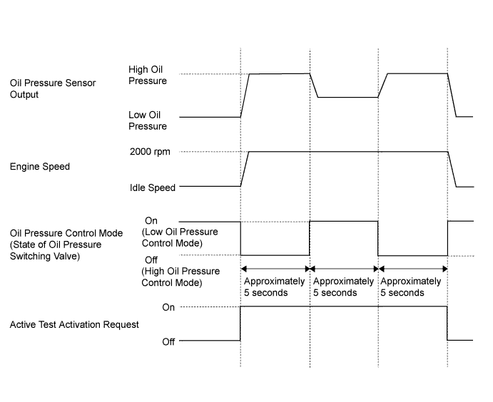
-
-
-